
Rotary electric machine

a rotary electric machine and rotor technology, applied in the direction of synchronous machines, windings, dynamo-electric components, etc., can solve the problems of loud wind splitting noise with the rotor, and achieve the effect of suppressing the formation of unevenness

Active Publication Date: 2013-07-30
MITSUBISHI ELECTRIC CORP
View PDF13 Cites 17 Cited by
  • Summary
  • Abstract
  • Description
  • Claims
  • Application Information

AI Technical Summary

Benefits of technology

The design suppresses the formation of unevenness on the inner circumferential surfaces of coil end groups, reducing wind-splitting noise and enhancing output by ensuring equal conductor wire distribution across slots, while simplifying manufacturing by omitting complex neutral point connections.

Problems solved by technology

Thus, the number of conductor wires that are housed in the slots is different in each slot, and one disadvantage has been that unevenness occurs on the inner circumferential surfaces of the coil end groups of the stator winding, generating loud wind-splitting noise with the rotor.

Method used


Image

  • Rotary electric machine
  • Rotary electric machine
  • Rotary electric machine

Examples


Embodiment Construction

[0020]A preferred embodiment of the present invention will now be explained with reference to the drawings.

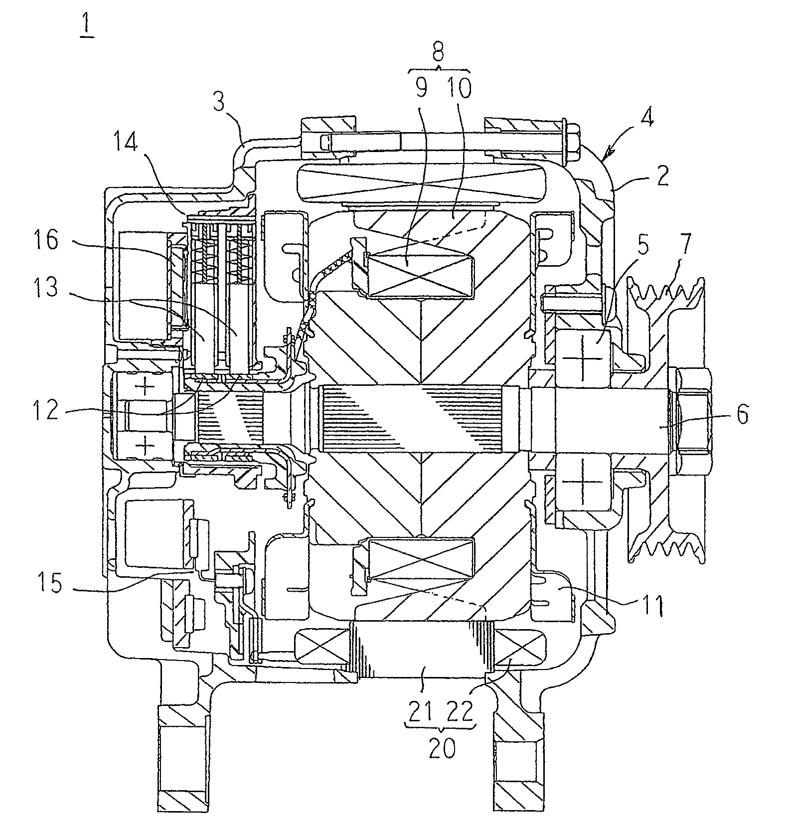
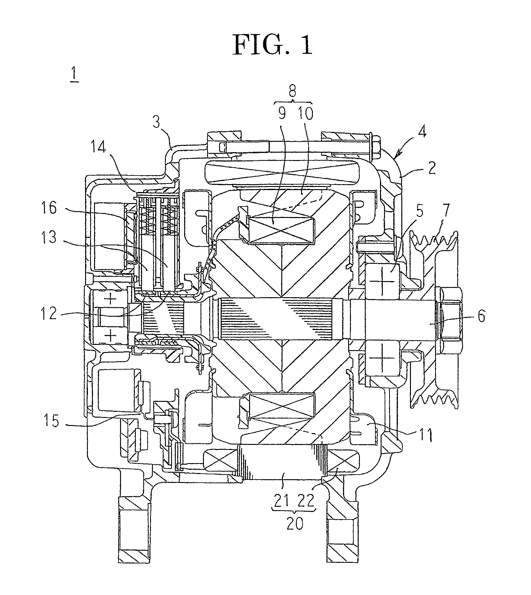
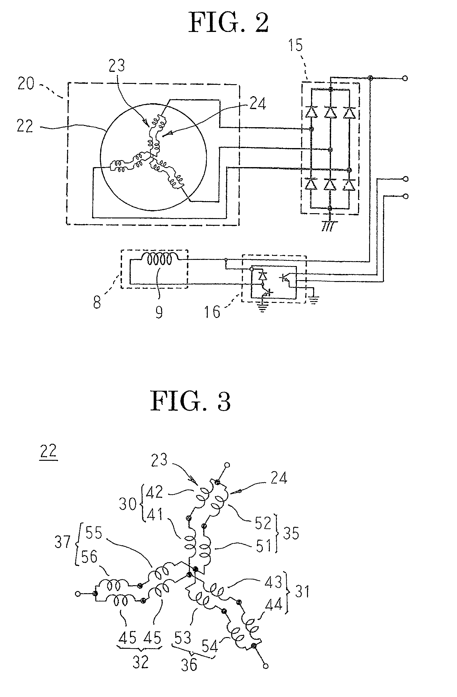
[0021]FIG. 1 is a longitudinal cross section that shows an automotive alternator according to a preferred embodiment of the present invention, FIG. 2 is an electrical circuit diagram for the automotive alternator according to the preferred embodiment of the present invention, FIG. 3 is a connection diagram for a stator winding in the automotive alternator according to the preferred embodiment of the present invention, FIG. 4 is an end elevation that shows a stator core that is used in the automotive alternator according to the preferred embodiment of the present invention, and FIG. 5 is a partial end elevation that explains a state in which conductor wires are mounted into the stator core in the automotive alternator according to the preferred embodiment of the present invention. Moreover, 1, 7, etc., through 67 in FIG. 4 represent slot numbers. FIG. 5 represents a state in whi...


PUM


Abstract

A stator winding is configured by connecting a first three-phase stator winding and a second three-phase stator winding in parallel. A U1-phase winding of the first three-phase stator winding is configured by connecting a U1-1-phase winding portion and a U1-2-phase winding portion in series, and a U2-phase winding of the second three-phase stator winding is configured by connecting a U2-1-phase winding portion and a U2-2-phase winding portion in series. The U1-1-phase winding portion and the U2-2-phase winding portion are m-turn wave windings, and the U2-1-phase winding portion and the U1-2-phase winding portion are n-turn wave windings (where n does not equal m). The U1-1-phase winding portion and the U2-1-phase winding portion are mounted into a first slot group, and the U1-2-phase winding portion and the U2-2-phase winding portion are mounted into a second slot group.

Description

BACKGROUND OF THE INVENTION[0001]1. Field of the Invention[0002]The present invention relates to a rotary electric machine such as an automotive alternator, and particularly relates to a mounting construction for a stator winding that is wound into a wave winding in a stator core in which slots are formed at a ratio of two slots per phase per pole.[0003]2. Description of the Related Art[0004]In conventional rotary electric machines, a stator winding is configured by wye-connecting a U-phase winding, a V-phase winding, and a W-phase winding in each of which a first winding and a second winding that have a phase difference of 30 electrical degrees from each other are connected in series, and the first winding and the second winding are each configured by connecting a plurality of windings in parallel (see Patent Literature 1, for example).[0005]Patent Literature 1: Japanese Patent Laid-Open No. 2010-136459 (Gazette: FIG. 15)[0006]In conventional rotary electric machines according to P...

Claims


Application Information

Patent Timeline
Patent Type & Authority Patents(United States)
IPC IPC(8): H02K1/00
CPCH02K3/28H02K19/22H02K3/12
Inventor KIMURA, TAKAHIROTANAKA, KAZUNORIOONISHI, YUKIYOSHI
Owner MITSUBISHI ELECTRIC CORP
Learn More