Fluid ejection device, program, and fluid ejection method
a technology of fluid ejection and nozzle, which is applied in the direction of visual presentation using printers, instruments, inking apparatus, etc., can solve the problems of extremely small nozzle spacing of nozzle rows and degraded image quality of printed images, so as to minimize such degradation of image quality and reduce the effect of printing image quality
- Summary
- Abstract
- Description
- Claims
- Application Information
AI Technical Summary
Benefits of technology
Problems solved by technology
Method used
Image
Examples
first embodiment
[0097]FIG. 9 is a drawing illustrating a halftoning process according to a first embodiment. In the first embodiment, the printer driver associates the center portion of the dither mask with the upper edge portion of the first band data and the lower edge portion of the fourth band data in the corrected 256-level data and performs the halftoning process. For band data to be assigned to heads 31 that are not situated at the edges in the paper width direction, the printer driver assigns a dither mask comparable to that of the comparative example (FIG. 8).
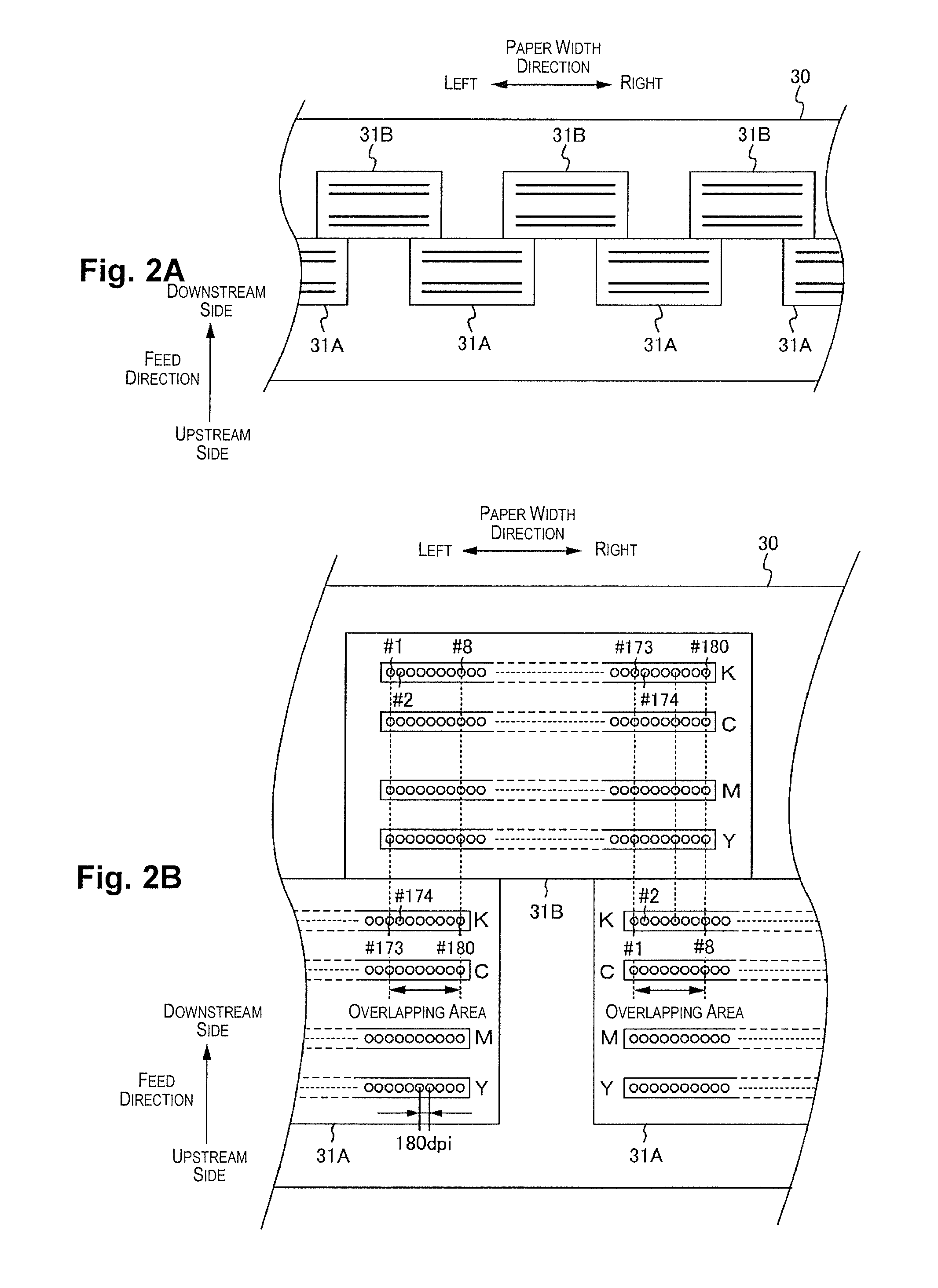
[0098]Let the number of pixels arranged in the paper width direction in the upper edge portion of the first band data with which the center area of the dither mask is associated be equal to the number of overlapping nozzles at the upper edge side of the other heads 31 excepting the first head 31(1). Here, because the number of overlapping nozzles at the upper edge side of the other heads 31 is eight, the number of pixels arranged in t...
third embodiment
[0108]FIG. 11 is a drawing illustrating a dither matrix association method according to a third embodiment. The preceding second embodiment uses threshold values obtained through inversion in the paper width direction of threshold values which are associated with data that is adjacent to the upper edge portion of the first band data and to the lower edge portion of the fourth band data. Therefore, in FIG. 10B, identical threshold values are associated with raster #3 and raster #4. Consequently, pixels having small threshold values and likely to have a dot generated become arranged in the paper width direction, whereas pixels having large threshold values and unlikely to have a dot generated become arranged in the feed direction.
[0109]Thus, according to the third embodiment, the printer driver associates with the upper edge portion of the first band data threshold values obtained through inversion in the paper width direction of threshold values of a dither mask associated with data ...
second embodiment
[0113]FIG. 12 is a drawing illustrating a print data creation process according to a second embodiment. In the first embodiment described previously, the nozzles of the upper edge portion of the first head 31(1) situated closest to the upper edge in the paper width direction and the nozzles of the lower edge portion of the fourth head 31(4) situated closest to the lower edge in the paper width direction are used in printing. For this reason, not only the upper edge area or lower edge area of the dither mask with a dot generation rate of 50%, but also the center area of the dither mask with a dot generation rate of 100%, are associated with the 256-level data assigned to the nozzles of the upper edge portion of the first head 31(1) and with the 256-level data assigned to the nozzles of the lower edge portion of the fourth head 31(4). This has the effect of preventing light printing of the edge portions of the image.
[0114]In contrast to this, according to the second embodiment, nozzle...
PUM
 Abstract
Description
Claims
Application Information
 - R&D Engineer
- R&D Manager
- IP Professional
- Industry Leading Data Capabilities
- Powerful AI technology
- Patent DNA Extraction
Browse by: Latest US Patents, China's latest patents, Technical Efficacy Thesaurus, Application Domain, Technology Topic.
© 2024 PatSnap. All rights reserved.Legal|Privacy policy|Modern Slavery Act Transparency Statement|Sitemap


