Two cycle engine and two cycle engine tool

a two-cycle engine and tool technology, applied in the field of two-cycle engines, can solve the problems of increasing the amount of total hydrocarbons (thc) included in the discharge gas, lowering the output of the engine, etc., and achieve the effect of clean and powerful two-cycle engine tools, and suppressing the reduction of the output of the two-cycle engin

Inactive Publication Date: 2013-08-06
KOKI HLDG CO LTD
View PDF12 Cites 5 Cited by
  • Summary
  • Abstract
  • Description
  • Claims
  • Application Information

AI Technical Summary

Benefits of technology

[0008]The present invention is made by taking the problems mentioned above into consideration, and an object of the present invention is to provide a two cycle engine which effectively suppresses a reduction of an engine output and an increase of total hydrocarbons (THC) in a discharged gas which are caused by an intrusion of a combustion gas into a crank chamber. Further, the other object of the present invention is to provide a two cycle engine tool provided with the two cycle engine mentioned above.
[0021]According to the present invention, since the combustion gas flowing backward to the internal space of piston is held in the internal space of piston, thereby preventing the combustion gas from making an intrusion into the crank chamber, it is possible to effectively suppress the reduction of the output of the two cycle engine and the increase of the total hydrocarbons (THC) in the discharged gas. Further, it is possible to achieve a clean and powerful two cycle engine tool.

Problems solved by technology

However, since a pressure within a cylinder (a combustion chamber) is higher than a pressure within the internal space of piston in an early stage of the scavenging stroke, there is a problem that the combustion gas within the cylinder flows backward to the internal space of piston through the scavenge air port, the scavenge air passage, the scavenge air inflow port, and the scavenge air communication port, and further intrudes into a crank chamber.
As a result, there is a problem that an output of an engine is lowered, and an amount of total hydrocarbons (THC) included in a discharge gas is increased.

Method used


Image

  • Two cycle engine and two cycle engine tool
  • Two cycle engine and two cycle engine tool
  • Two cycle engine and two cycle engine tool

Examples


Embodiment Construction

[0033]A description will be given below of a best mode for carrying out the present invention with reference to the attached drawings.

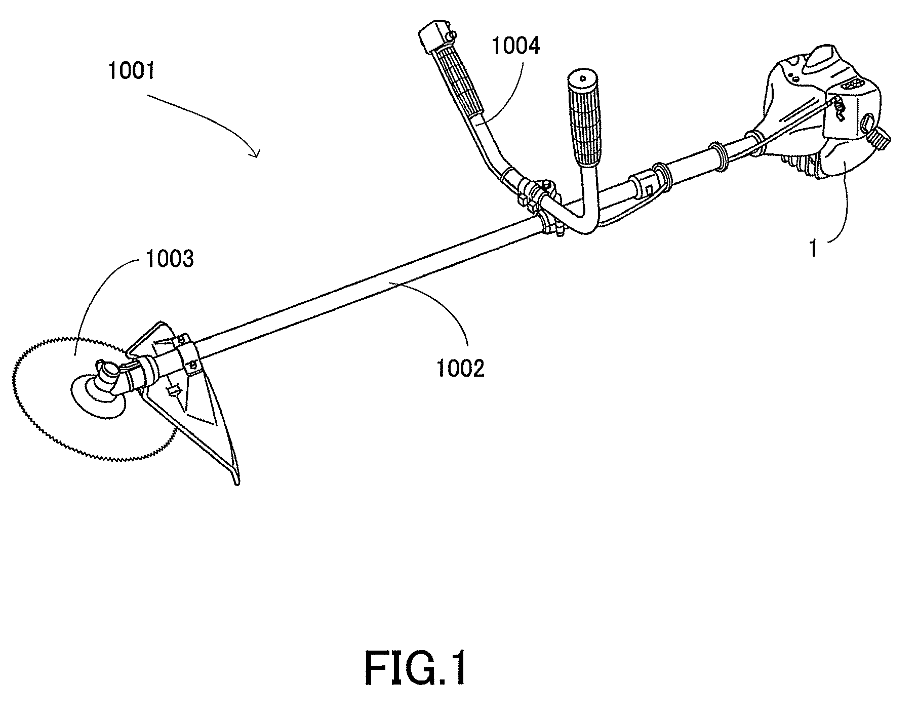
[0034]FIG. 1 shows the exterior of a bush cutter 1001 on which a two cycle engine (hereinafter referred to as an engine) 1 according to the present invention is mounted. As shown in FIG. 1, a rotary blade 1003 is attached to a front end of a control rod 1002 of the bush cutter 1001, and an engine 1 is attached to a rear end of the control rod 1002. The power of the engine 1 is supplied to the rotary blade 1003 via a drive shaft that is inserted into the control rod 1002. An operator grips a handle 1004 attached to the control rod 1002 to operate the bush cutter 1001.

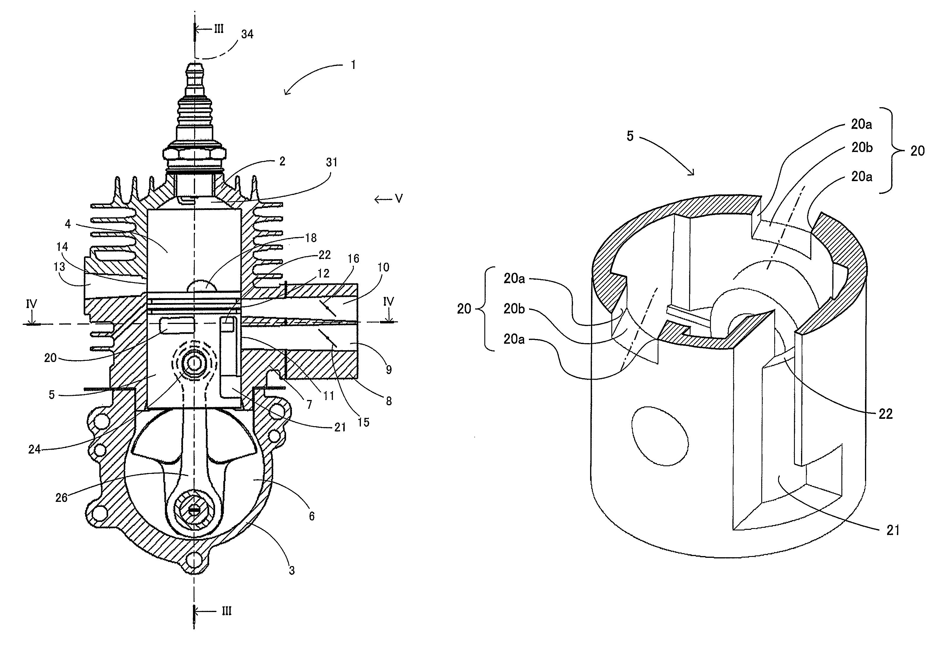
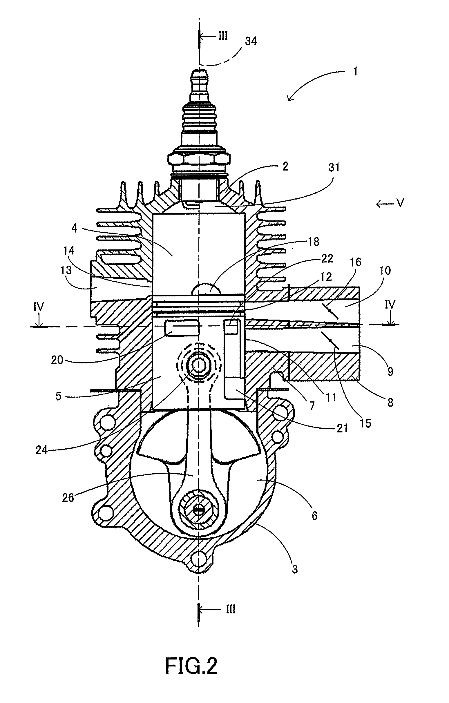
[0035]A description will be given of a structure of the engine 1 with reference to FIGS. 2 to 6.

[0036]FIG. 2 is an elevated view in section cutting the engine 1 by a plane including a center line equally dividing the exhaust port 14 in a circumference direction of the cylinder 4 and a cyli...


PUM


Abstract

The invention provides a two cycle engine which effectively suppresses an intrusion of a combustion gas into a crank chamber. Further, the invention provides a two cycle engine tool provided with the two cycle engine mentioned above. An engine is provided with a cylinder having two scavenge air ports at different positions in a cylinder circumference direction, and scavenge air inflow ports communicating individually with these two scavenge air ports via a scavenge air passage, and a piston in which two scavenge air communication ports are formed at positions corresponding to the scavenge air inflow ports, and is structured to swirl the gas flowing into the piston from the cylinder through the scavenge air passage, in an upper portion of the internal space of the piston, and retains the gas in the upper portion of the internal space of the piston.

Description

BACKGROUND OF THE INVENTION[0001]1. Field of the Invention[0002]The present invention relates to a two cycle engine, and more particularly to a two cycle engine which is suitable for a handheld tools powered by an engine such as a bush cutter, a chain saw, a blower and the like, and a two-cycle-engine-powered tool provided with the two cycle engine.[0003]2. Description of the Related Art[0004]Conventionally, there have been proposed a lot of inventions which relate to a two cycle engine reducing an outflow (blow-by) of an air-fuel mixture within a cylinder into an exhaust port, in a scavenging process.[0005]For example, in Patent Literature 1, there is proposed a stratified scavenging two cycle engine which scavenges a combustion gas by making a lead air having flown into an internal space of piston through a lead air port and a lead air flow path in a suction stroke, and making the lead air flowing into the internal space of piston flow into a cylinder through a scavenge air commun...

Claims


Application Information

Patent Timeline
Patent Type & Authority Patents(United States)
IPC IPC(8): F02B25/00
CPCF02B25/04F02B63/02F02F3/24F02M35/1019F02B2075/025F02M25/0743F02M35/1017Y02T10/146F02M26/37Y02T10/12
Inventor YASUTOMI, TOSHINORIOHTSU, SHINKIKAMIMURA, JUNICHIISHIDA, SHIGETOSHI
Owner KOKI HLDG CO LTD
Why Eureka
Try Eureka