Joystick controller

a joystick controller and controller technology, applied in the field of joystick controllers, can solve the problems of low digital resolution, poor reliability, pitting and contact bounce, etc., and achieve the effect of accurately sensed and new mechanical simplicity

Inactive Publication Date: 2013-08-06
BOKAM ENG
View PDF14 Cites 4 Cited by
  • Summary
  • Abstract
  • Description
  • Claims
  • Application Information

AI Technical Summary

Benefits of technology

[0011]The present invention comprises joystick controller which addresses the aforementioned deficiencies of the prior art by employing a unitary sensor surface structure having surface-mounted strain gauges configured as full bridges, one for each direction of joy stick motion. This unique strain gauge layout design permits a new level of mechanical simplicity not heretofore available in joystick controllers. There are essentially no moving parts to wear out. An elongated post or lever is, in the preferred embodiment, mechanically coupled to the sensor surface structure by a robust spring to provide a psychologically appealing physical motion of the lever during activation of the joystick controller. However, the post could optionally be directly affixed to the sensor surface structure so that forces applied transversely to the post will be accurately sensed without any discernable movement.
[0012]The remaining elements of the controller merely provide a sealed housing for a printed circuit board for conditioning the output of the strain gauge bridges and to provide a suitable mechanical interface with a support structure for mounting the joystick controller. The joystick controller of the present invention is thus accurate, durable and reliable, simple in configuration and therefore of relatively low cost to manufacture and assemble. Its relatively simple mechanical configuration results in a commensurately small assembly that can be used as a replacement for most existing industrial joystick controllers without modification to existing support structure.

Problems solved by technology

Most of these joysticks are able to sense the motion of the shaft in one of four or eight different radial directions but do not sense how far the shaft has moved in the chosen direction.
However, the digital resolution is exceedingly low (one binary bit of information for each of the eight detectable directions of shaft motion).
Also, the electrical contacts in mechanically operated switches are subject to wear, corrosion, contamination, pitting and contact bounce.
Joysticks of this type lack the resolution and reliability needed for control of powered wheelchairs, forklifts, machine tools, earth-moving machines, robotic devices, etc.
These approaches are more reliable than resistive potentiometers but are inherently non-linear (i.e., unlike resistive potentiometers which are normally fabricated to be very linear, the analog output signal from these inductive devices does not vary linearly with joystick shaft position).
Electronic compensation of this inherent non-linearity is feasible but adds to cost and complexity.
Thus, it can be seen that mechanical assemblies for analog joysticks tend to be mechanically complex and electrical assemblies for digital joysticks tend to be electronically complex.
Both such complexities increase cost and reduce reliability.
This approach limits lever movement and generates material fatigue that can lead to reliability problems.
This controller solved many of the noted deficiencies of the patent art, but introduced end of travel anomalies that detracted from overall performance as will be described hereinafter.

Method used


Image

  • Joystick controller
  • Joystick controller
  • Joystick controller

Examples


Embodiment Construction

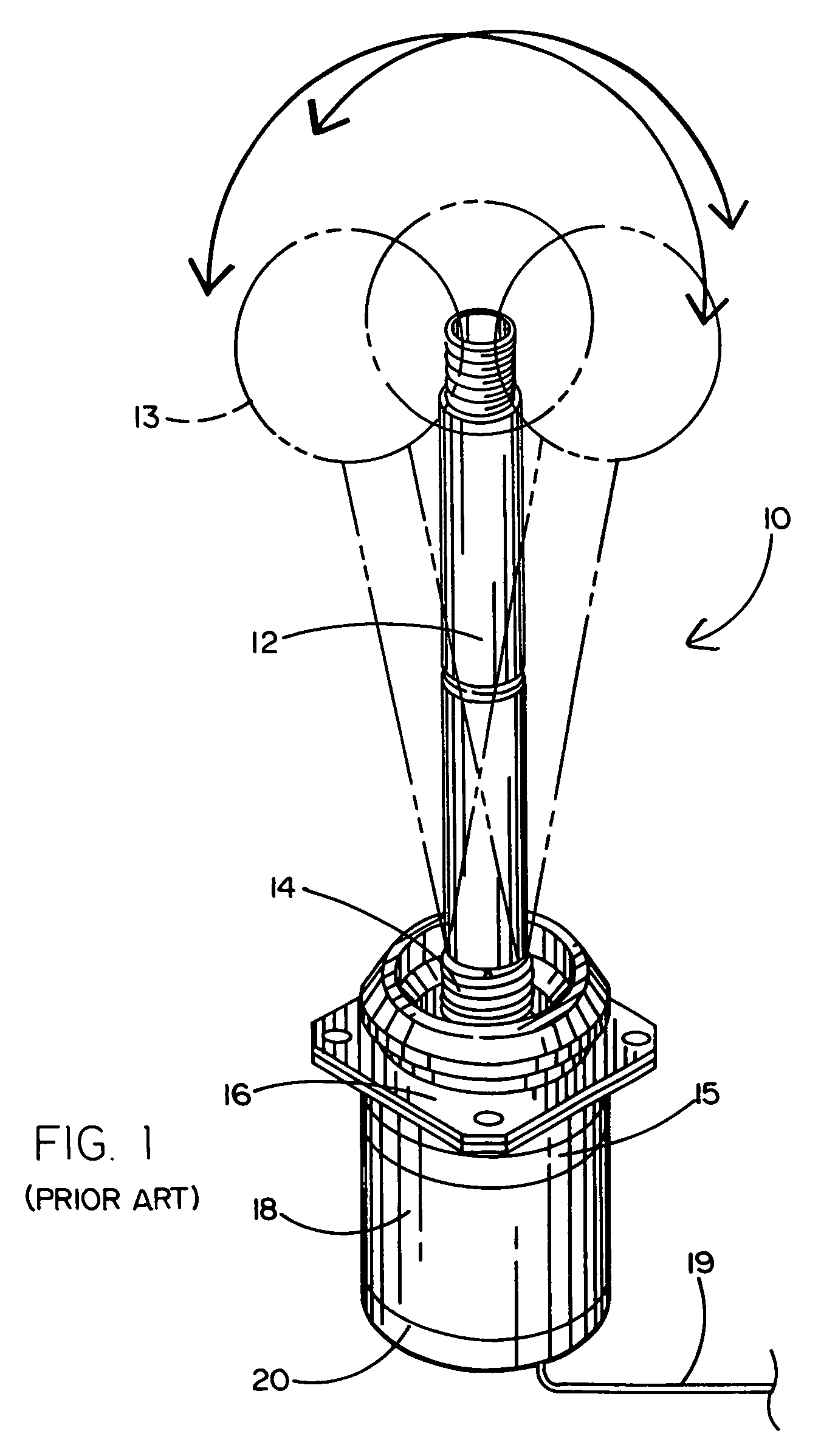
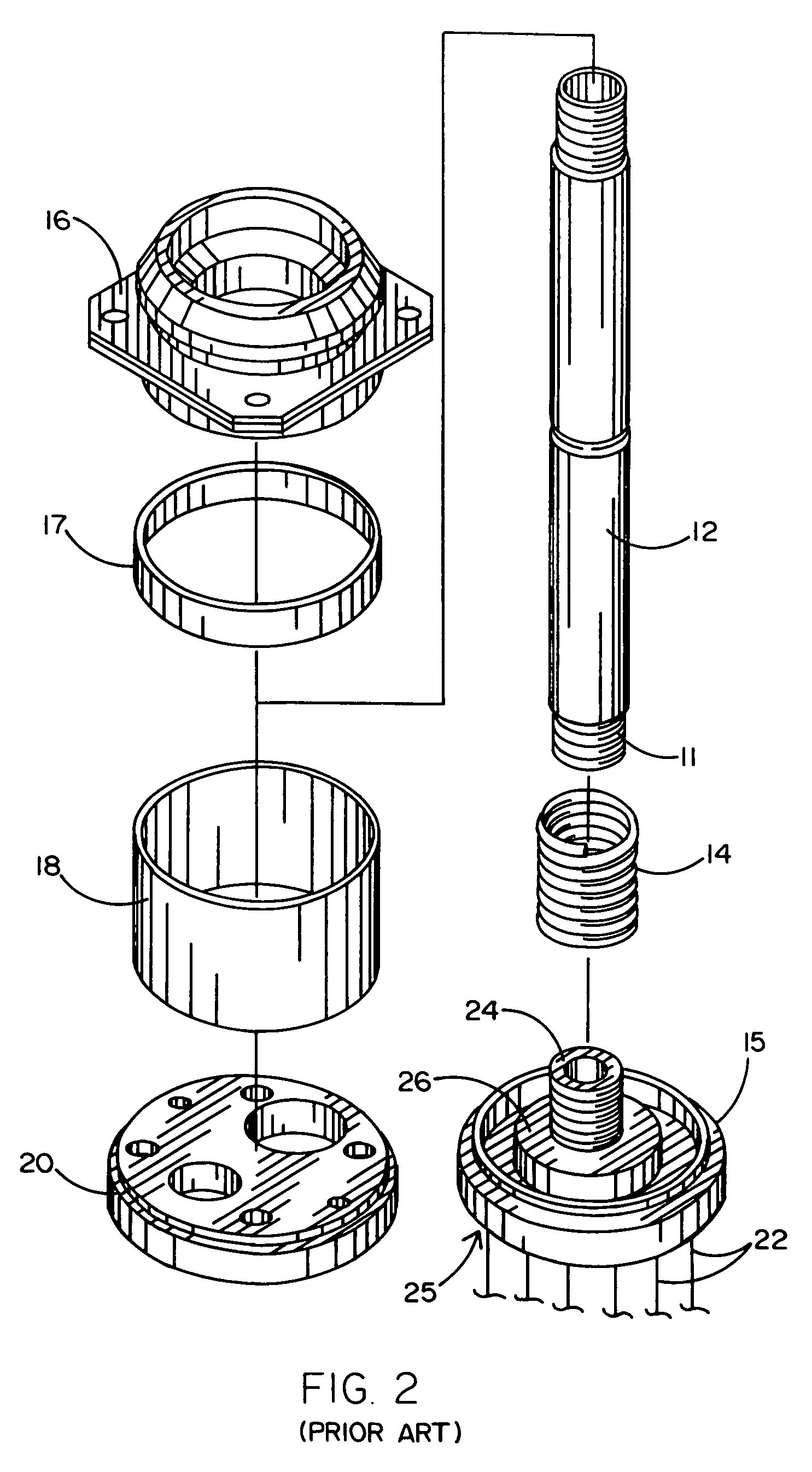
[0027]Referring to the accompanying drawings and FIGS. 1-3 in particular, it will be seen that a prior art joystick controller 10, comprises an elongated post 12, a helical coil spring 14, a sensor structure 15, a top member 16 and a tubular housing 18. Housing 18 is preferably closed off by a bottom member 20, the latter having one or more apertures to pass a cable 19. A collar 17 is preferably located between top member 16 and sensor structure 15. The post 12 may have a spherical knob 13 threaded onto the upper end to facilitate comfortable contact with the palm of a hand or the like. A flexible boot (not shown) may be used to enclose post 12 and spring 14 to prevent dust and dirt from contaminating those components. Post 12 has a lower threaded end 11 for threadably engaging spring 14.

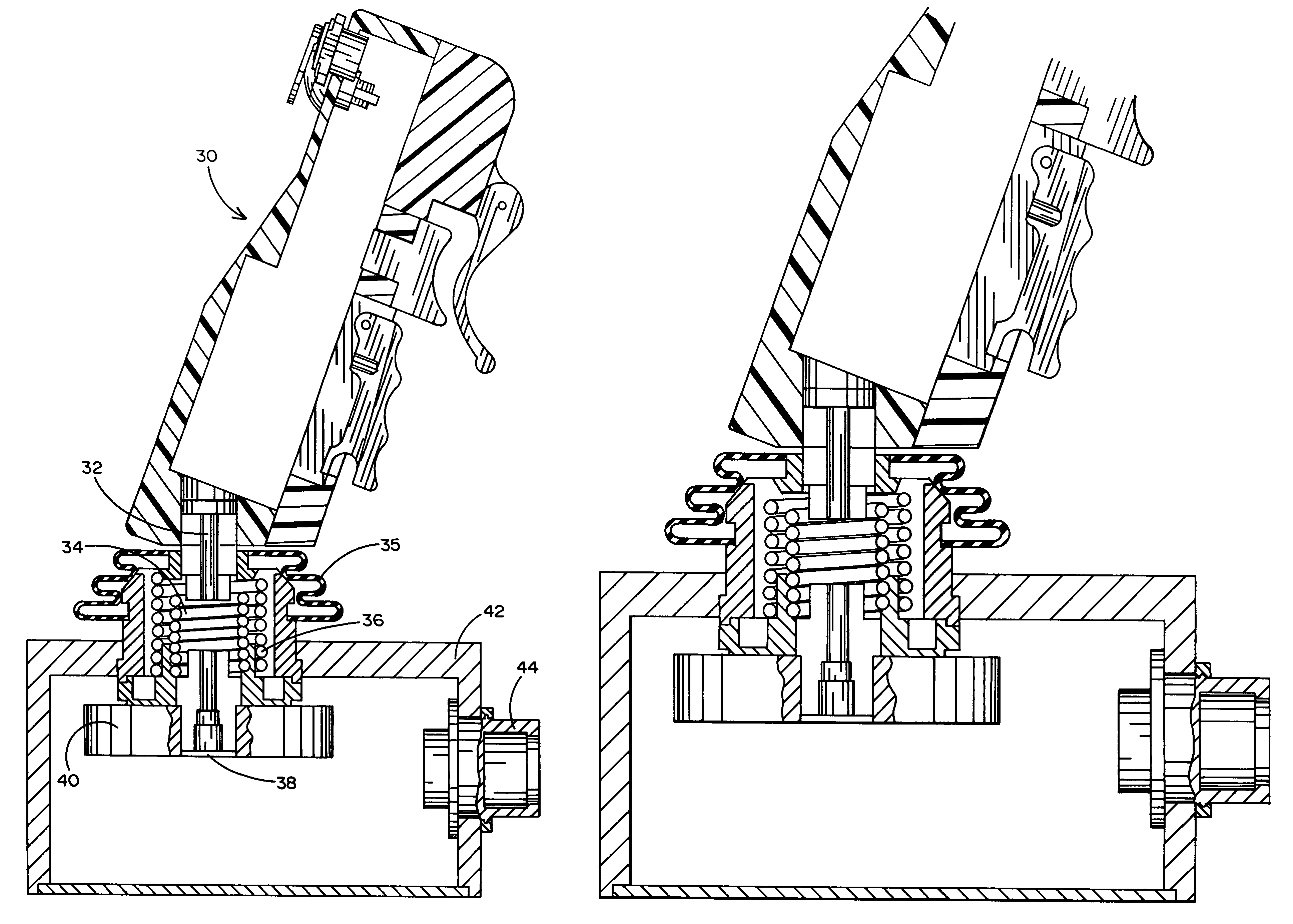
[0028]Unfortunately, the prior art joystick controller of FIGS. 1-3 has a significant disadvantage relating to end of travel anomalies. Whenever the post 12 has been pushed to its mechanical limit (...


PUM


Abstract

A joystick controller in two-dimensional and one-dimensional versions. The 2-D version employs a unitary sensor surface structure having eight surface-mounted or deposited strain gauges configured as two full bridges or four surface-mounted or deposited strain gauges configured as two half bridges, one for the X direction and one for the Y direction. This unique strain gauge layout design permits a new level of mechanical simplicity not heretofore available in joystick controllers. There are essentially no moving parts to wear out. An elongated post or lever is, in the preferred embodiment, mechanically coupled to the sensor surface structure by a pair of co-axial robust coil springs to provide a psychologically appealing physical motion of the lever during activation of the joystick controller. In the 1-D version, a rotatable cam element is positioned between parallel elongated leaf springs. The cam element is positioned at one end of the springs. The other end of the springs is mechanically coupled to a strain gauge layout which comprises a full bridge or half bridge sensor.

Description

BACKGROUND OF THE INVENTION[0001]1. Field of the Invention[0002]The present invention relates to a joystick controller typically used for controlling heavy machinery, industrial equipment and the like. The invention relates more specifically to an improved joystick controller which employs strain gauges which are placed in tension and compression to indicate the position and direction of a moveable post.[0003]2. Background Art[0004]Joystick controllers or actuators provide an electrical signal responsive to the displacement of a rod or lever from a neutral position. Preferably, they permit accurate manifestations of lever movement in any direction (i.e., 360°) by generating signals along two orthogonal exes (i.e., x and y) based upon the respective displacement along each axis. Typically, they utilize variable resistors coupled to the lever through complex mechanical assemblies. Various examples of such assemblies are shown in prior art U.S. Pat. Nos. 4,306,208; 4,459,440; 4,587,510...

Claims


Application Information

Patent Timeline
Patent Type & Authority Patents(United States)
IPC IPC(8): G09G5/08
CPCG05G9/047G05G2009/04725G05G2009/04762
Inventor KAMENTSER, BORISKAMENTSER, EUGENIA
Owner BOKAM ENG
Why Eureka
Try Eureka