Application data flow management in an IP network

a technology of application data flow and network, applied in data switching networks, instruments, digital transmission, etc., can solve the problems of inability to integrate modules in devices, and inability to realize software modules, so as to facilitate the creation of cross-service control and reduce the complexity of protocol analysis

Active Publication Date: 2013-08-06
TELECOM ITALIA SPA
View PDF35 Cites 131 Cited by
  • Summary
  • Abstract
  • Description
  • Claims
  • Application Information

AI Technical Summary

Benefits of technology

[0027]The objective of the present invention is therefore to provide a network-based application control architecture which enables the aforementioned drawbacks of the P-CUBE architecture to be at least in part overcome.
[0031]Such a two-level control architecture, wherein the application flow interception level is separated from the proper correlation and control level, reduces the complexity of the analysis of a protocol as compared to classic approaches (e.g., NERL), leaving the actions corresponding to the traffic pattern matching (hence the ones that can be easily carried out by hardware systems for the Deep Packet Inspection) to be carried out at a low level and delegating to a high level aggregation of the information and management of the state transitions. Additionally, this approach considerably facilitates the creation of a cross-service control, i.e., one that allows simultaneous access to different services by the same user to be monitored.

Problems solved by technology

Regarding the approach based on the application proxy, the Applicant has noticed that it is particularly burdensome from the standpoint of the device design, in so far as it calls for the realization of an application emulation module for each service / protocol that it is intended to support.
It should moreover be noted that in certain cases the realization of the software module may not be feasible, and hence the module may not be available for integration in the device, for example, when the service uses proprietary and / or undisclosed protocols (such as some protocols used for Gaming, P2P services, VoIP, EMAIL / SMS / .
In fact, for these applications, by placing the probe where the traffic is cyphered it could lead to not distinguish the application states, whilst by placing the probe where the traffic is not cyphered, it could lead to lose data regarding the media traffic, on which enforcement should be effected.

Method used


Image

  • Application data flow management in an IP network
  • Application data flow management in an IP network
  • Application data flow management in an IP network

Examples


Embodiment Construction

[0046]The following description is presented to enable a person skilled in the art to make and use the invention. Various modifications to the embodiments will be readily apparent to those skilled in the art, and the generic principles herein described may be applied to other embodiments and applications without departing from the scope of the present invention. Thus, the present invention is not intended to be limited to the embodiments shown, but is to be accorded the widest scope consistent with the principles and features disclosed herein and defined in the attached description and claims.

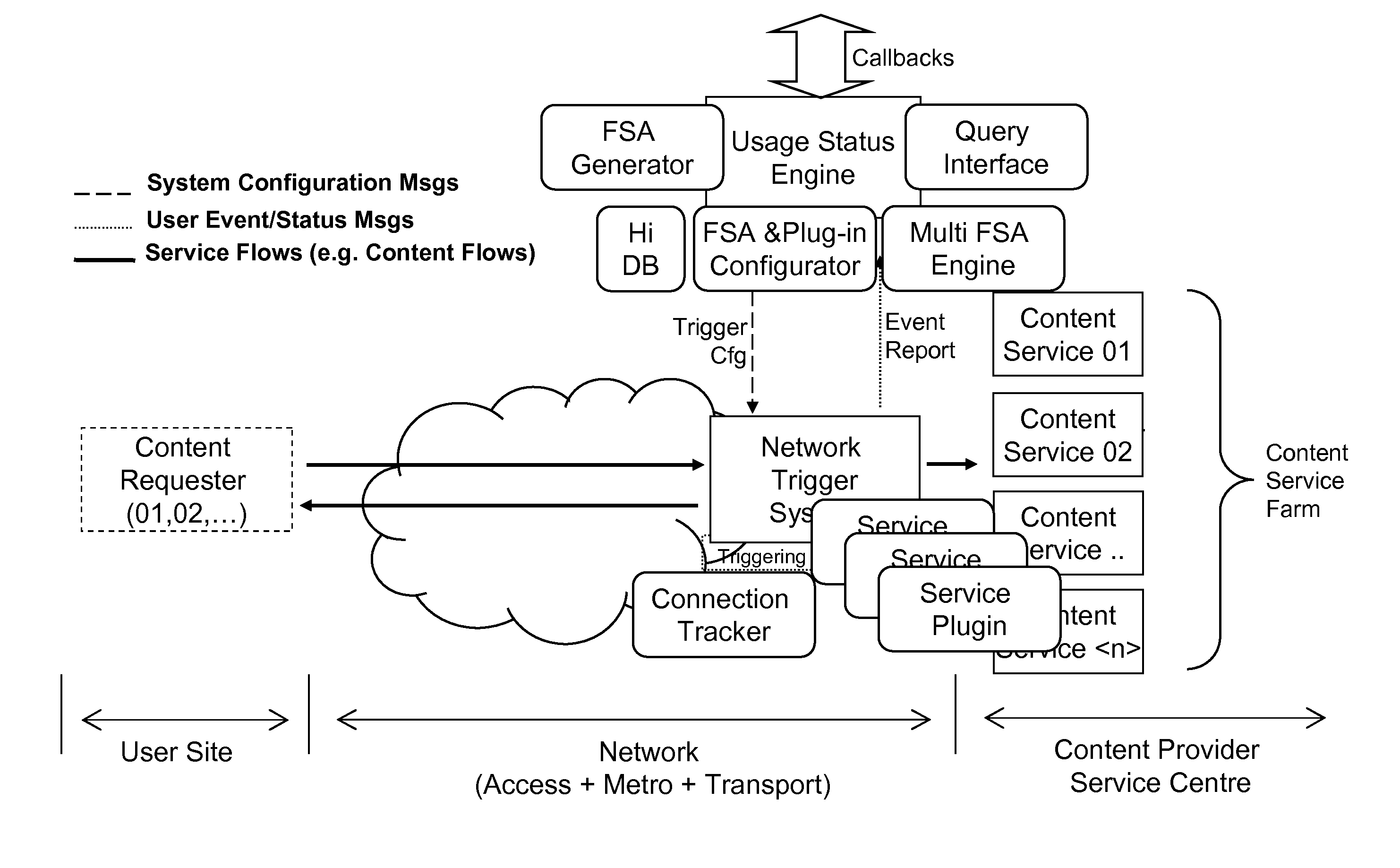
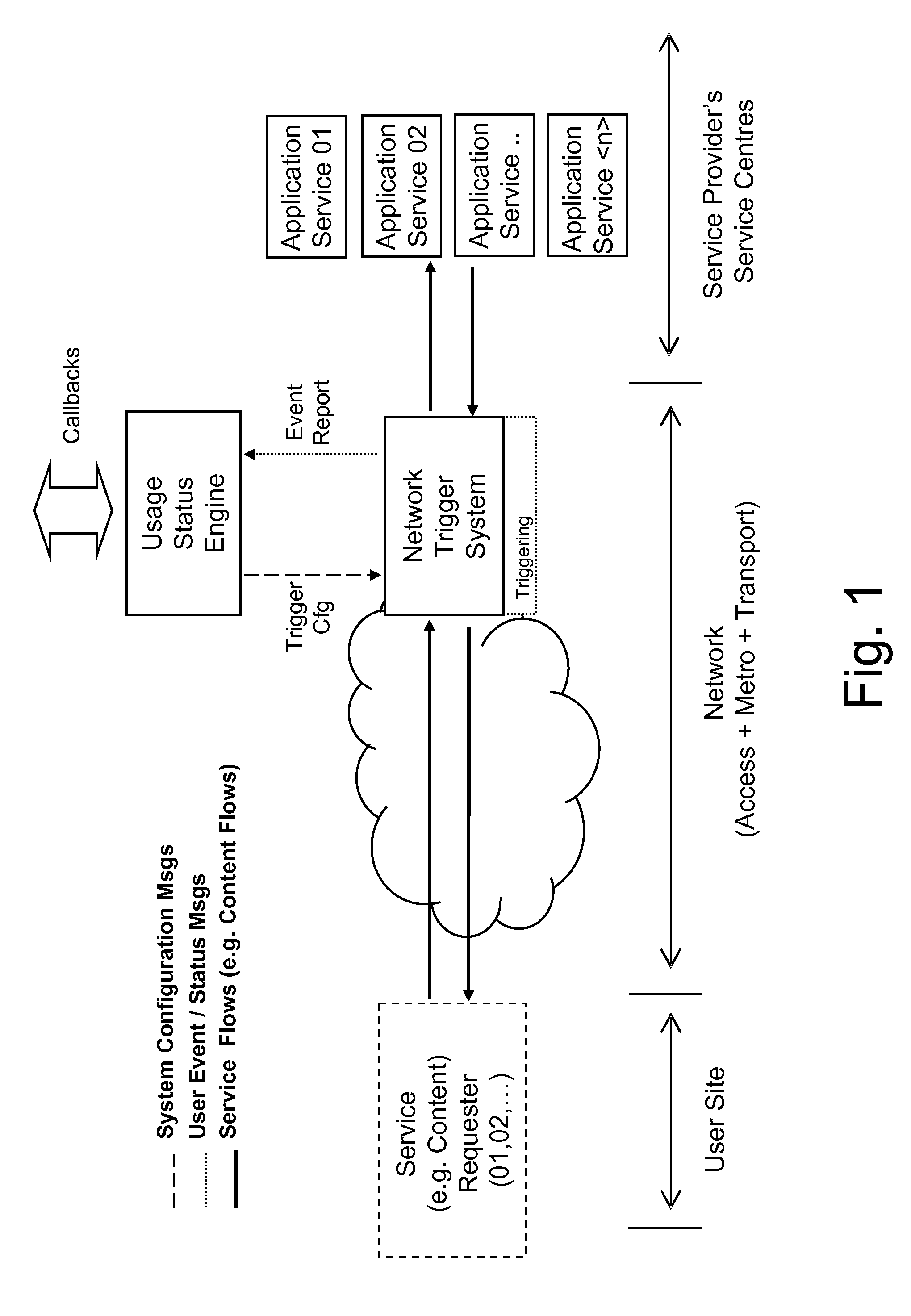
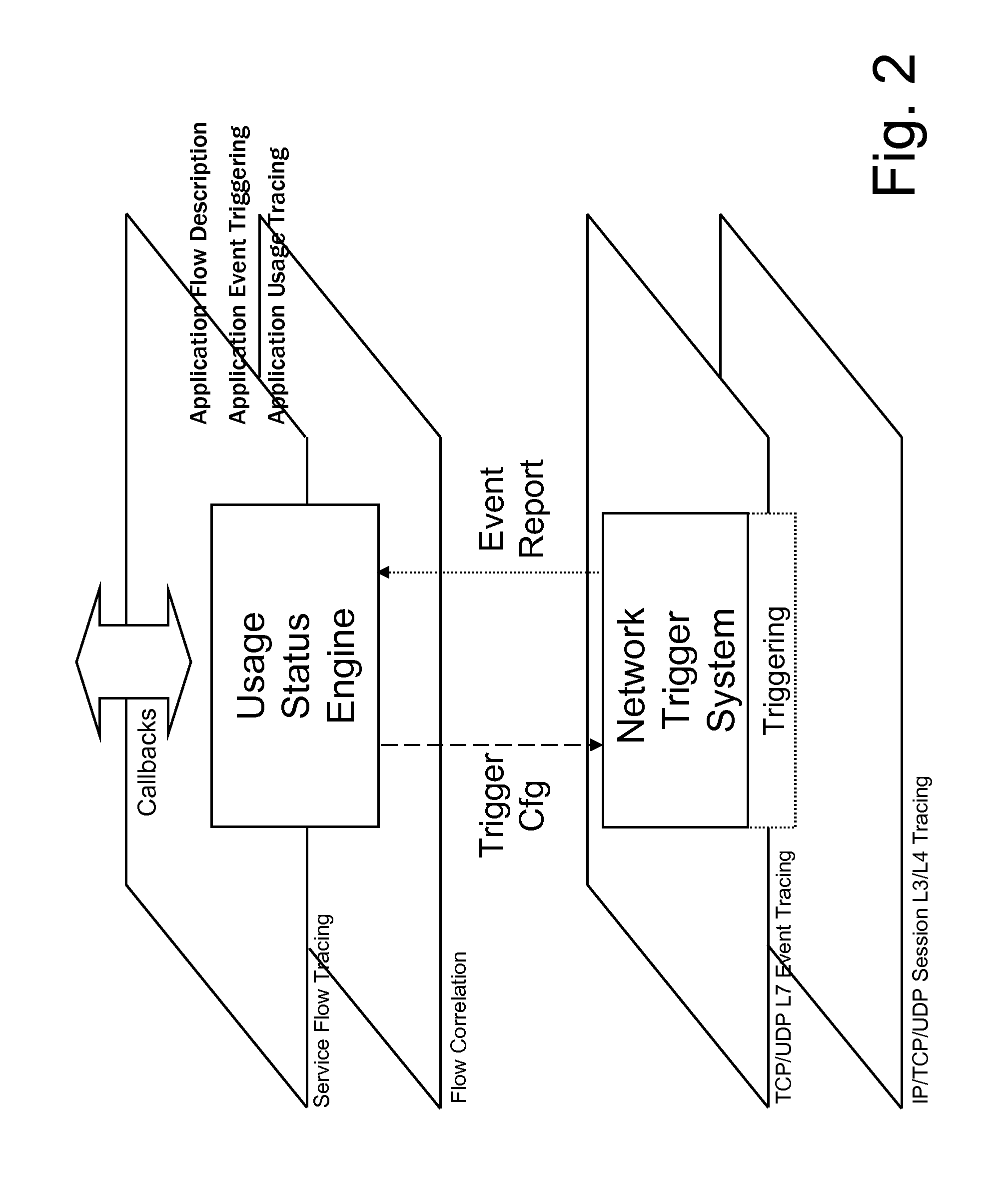
[0047]The present invention is based on a two-level, multiprobe, network-based application control (NBAC) architecture which envisages the use of a centralized correlation component based on finite state logics (FSA, Finite State Automaton). At a general level, the NBAC acts between a generic Service Requester and one or more Application Services and enables Non-Session-based services (such as ...


PUM


Abstract

Disclosed herein is a two-level, network-based application control (NBAC) architecture for monitoring services provided via a packet-based network. The NBAC architecture includes a Network Trigger System provided at a network level to analyze data flows relating to services to be monitored to detect occurrence of configurable events, and to generate and send event reports; and a Usage Status Engine provided at a control level to configure the Network Trigger System to detect occurrence of events of interest, and to receive and process the event reports from the Network Trigger System to monitor the services.

Description

CROSS REFERENCE TO RELATED APPLICATIONS[0001]This is a U.S. National Phase Application under 35 U.S.C. 371 of International Application No. PCT / EP2008 / 066275, filed Nov. 26, 2008, which was published Under PCT Article 21(2), the entire contents of which are incorporated herein by reference.TECHNICAL FIELD OF THE INVENTION[0002]The present invention relates in general to application data flow management in an IP network, and in particular to a two-level, network-based application control architecture for monitoring services, preferably Non-Session-based services, provided via a packet-based network.BACKGROUND ART[0003]Services that can be supplied to end users over a data network can be categorized in Session-based services and Non-Session-based services. Generally, services belonging to the first category are those that enable a multimedia session (e.g., Audio and / or Video) to be provided by two network end points (software user agents) with the support of a signalling protocol towa...

Claims


Application Information

Patent Timeline
Patent Type & Authority Patents(United States)
IPC IPC(8): G06F15/173
CPCH04L41/06H04L41/5009H04L43/12H04L43/0811H04L41/5032
Inventor MAFFIONE, EUGENIO MARIAGAROFALO, ANGELOBINCOLETTO, LUCA
Owner TELECOM ITALIA SPA
Why Eureka
Try Eureka