Tool extension

a tool extension and tool technology, applied in the direction of wrenches, screwdrivers, manufacturing tools, etc., can solve the problems that the user cannot easily and suitably and effectively operate the typical combination tool or tool extension, and achieve the effect of convenient and quick and convenient and safe attachment or mounting, easily and suitably actuated or operated by the user

Active Publication Date: 2013-08-13
CHIANG WEN HUNG
View PDF9 Cites 15 Cited by
  • Summary
  • Abstract
  • Description
  • Claims
  • Application Information

AI Technical Summary

Benefits of technology

[0008]The primary objective of the present invention is to provide a combination tool or tool extension including a structure for easily and quickly and readily and safely attaching or mounting or securing a tool stem to an outer covering or housing and for adjusting the tool stem relative to the outer covering or housing to the required extending position or location, and for allowing the tool extension to be easily and suitably actuated or operated by the user.
[0012]The shaft includes a retaining ring attached thereto and slightly extended radially and outwardly from the shaft for selectively engaging with the detent and for frictionally engaging with the inner peripheral surface of the housing and for limiting the shaft to slide relative to the housing and for preventing the shaft from being disengaged from the housing.
[0015]The fetching device includes a gasket engaged into the barrel for engaging with the third spring biasing member and for retaining the third spring biasing member in the barrel and for preventing the third spring biasing member from being disengaged from the barrel, and also for further preventing the barrel from being disengaged from the shank.

Problems solved by technology

However, the typical combination tools or tool extensions comprise a control ferrule that may be moved in only one active direction relative to the tool extension to adjustably secure or couple the tool members or tool elements together, but the control ferrule may not be moved in the other direction relative to the tool extension to adjustably secure or couple the tool members or tool elements together, such that the typical combination tools or tool extensions may not be easily and suitably and effectively actuated or operated by the user, particularly when the typical combination tools or tool extensions are required to be attached or mounted or secured or coupled to the driving tools with the hands of the user, such as the tool handles, or hydraulic or pneumatic driving mechanisms or facilities or the like.

Method used


Image

  • Tool extension
  • Tool extension
  • Tool extension

Examples


Embodiment Construction

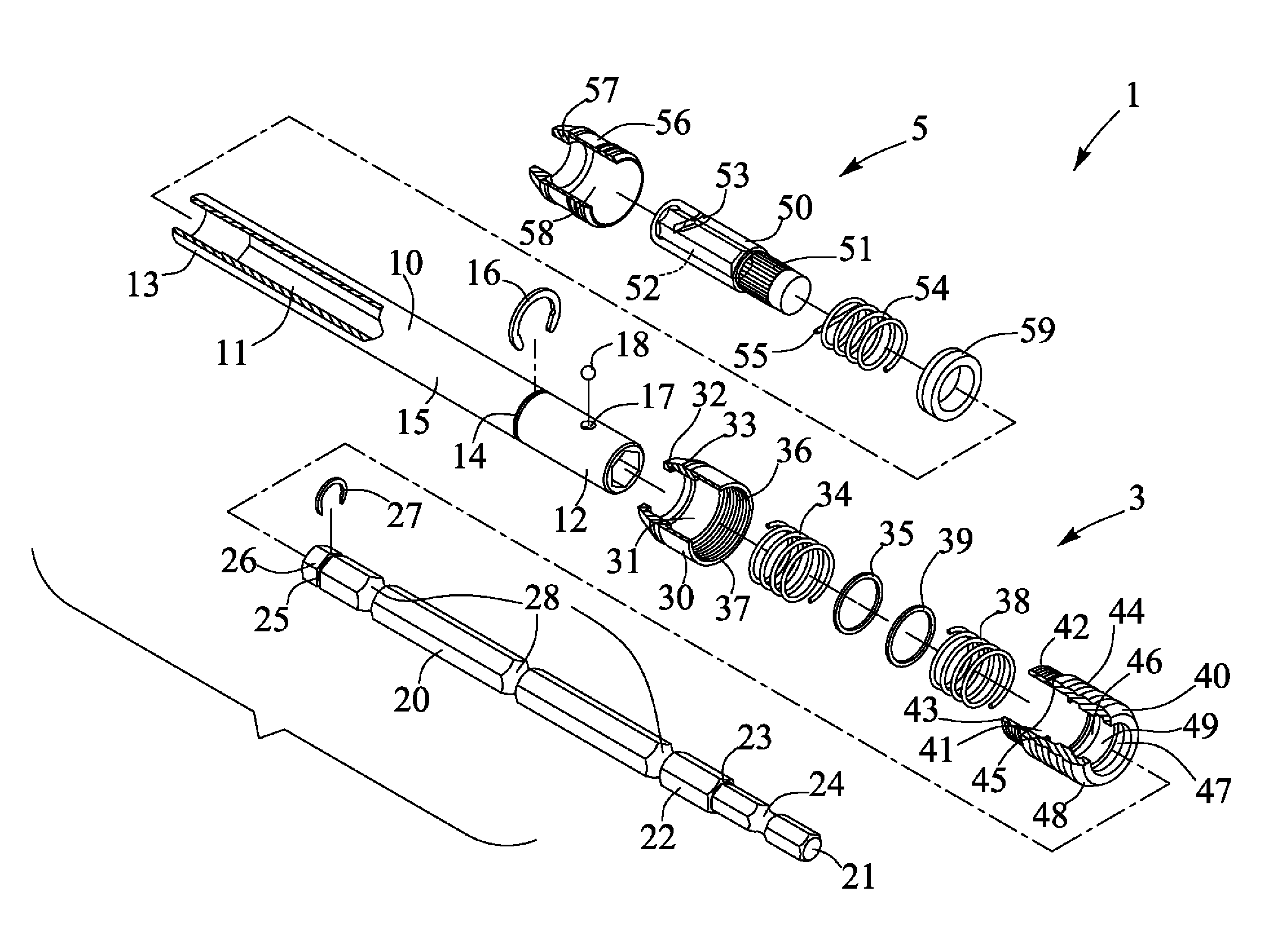
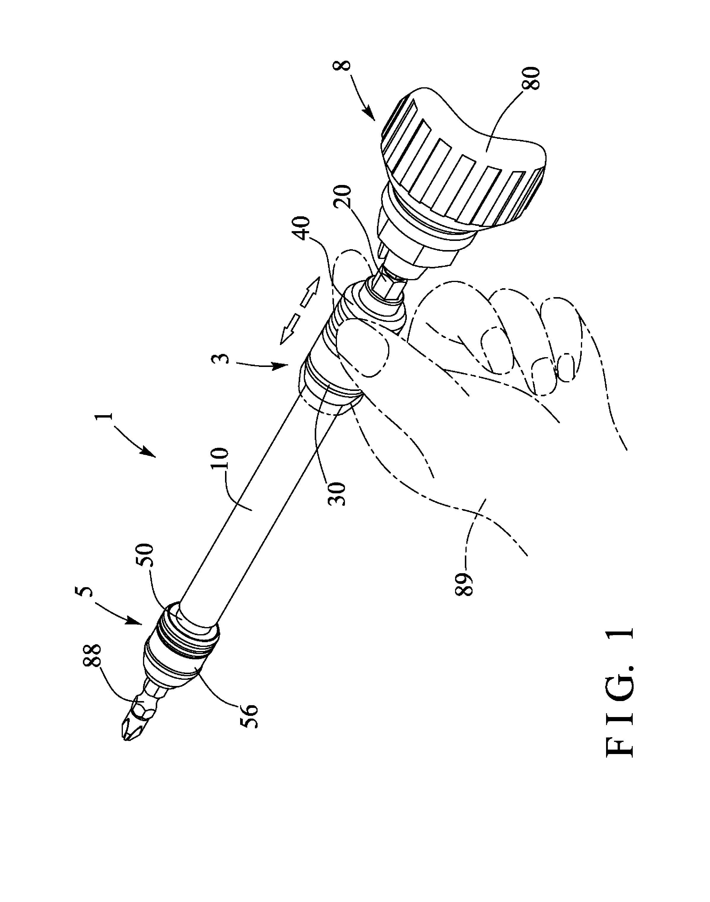
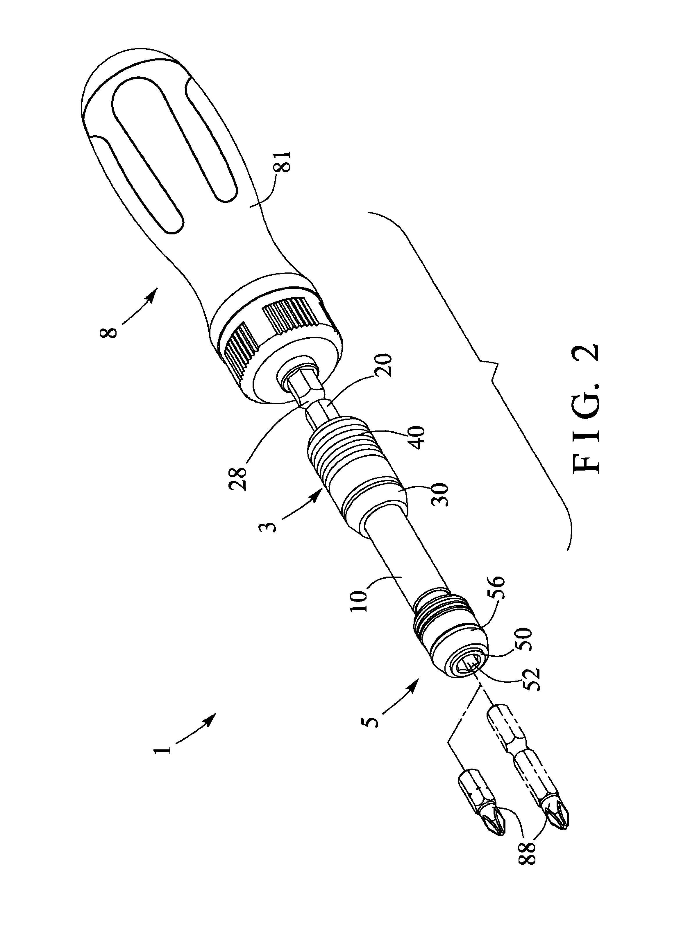
[0022]Referring to the drawings, and initially to FIGS. 1 and 2, a combination tool or tool extension 1 in accordance with the present invention is developed and provided for attaching or mounting or securing or coupling to a driving tool 8, such as the hydraulic or pneumatic driving mechanisms or facilities 80 (FIG. 1), the tool handles 81 (FIG. 2), or the like in order to be suitably rotated or driven by the driving tool 8. Referring next to FIGS. 3-4 and again to FIGS. 1 and 2, the tool extension 1 comprises a longitudinal arm or handle or tubular or cylindrical member or housing 10 including a longitudinal chamber or compartment or bore 11 formed therein, such as formed through the length thereof and having a non-circular cross section, and the housing 10 includes one end or first end portion 12 and the other or the second end portion 13.

[0023]The housing 10 further includes a peripheral slot 14 formed in the outer peripheral portion thereof and located at the middle or intermed...


PUM


Abstract

A tool extension includes a positioning ring engaged with a housing, a detent extendible into a bore of the housing, a shank attached to the housing for supporting a tool element, a shaft engaged in the housing and having two or more outer peripheral grooves for engaging with the detent, and a control device having a sleeve and a control ferrule secured together and engaged onto the housing, and two spring biasing members engaged with the positioning ring and the sleeve and the control ferrule, and the control ferrule includes two troughs for engaging with the detent and for defining an inner peripheral actuator between the troughs and for easily operating the sleeve and the control ferrule of the control device.

Description

BACKGROUND OF THE INVENTION[0001]1. Field of the Invention[0002]The present invention relates to a combination tool or tool extension, and more particularly to a combination tool or tool combination or tool extension including a structure for easily and quickly and readily and safely attaching or mounting or securing a tool stem to an outer covering or housing and for adjusting the tool stem relative to the outer covering or housing to the required extending position or location, and for allowing the tool extension to be easily and suitably actuated or operated by the user.[0003]2. Description of the Prior Art[0004]Typical combination tools or tool combinations or tool extensions comprise two or more tool members or tool elements adjustably secured or coupled together to form a retractable or telescopic structure and for allowing the tool extensions to secure or couple a driven tool member to the driving tools, such as the tool handles, or hydraulic or pneumatic driving mechanisms o...

Claims


Application Information

Patent Timeline
Patent Type & Authority Patents(United States)
IPC IPC(8): B25B23/16B25B13/00B25B23/00B25G1/00
CPCB25B23/0021B25B23/0035B25G1/00B25B23/16
Inventor CHIANG, WEN HUNG
Owner CHIANG WEN HUNG
Why Eureka
Try Eureka