Axle drive device for an axle of a motor vehicle, as well as motor vehicle

a technology for axles and motor vehicles, which is applied in mechanical devices, transportation and packaging, and transportation of vehicles, etc., can solve the problems of electrical drive assemblies not being able to be used, and the torque of another drive assembly cannot be delivered to the axle drive device, so as to achieve the same agility, reduce the size of the axle, and increase the agility of the motor vehicle

Inactive Publication Date: 2013-08-13
AUDI AG
View PDF20 Cites 5 Cited by
  • Summary
  • Abstract
  • Description
  • Claims
  • Application Information

AI Technical Summary

Benefits of technology

[0005]This is achieved, according to the invention, by the drive assembly being designed as an electrical drive assembly and the differential having at least one override unit. Therefore, first of all, the object is to use an electrical drive assembly to drive an axle. But at the same time, high agility of the motor vehicle is to be achieved. For this reason, at least one override unit is assigned to the differential. This linking of the electrically driven axle to the differential with the override unit can yield smaller dimensioning of the required electrical drive power, with agility remaining the same. The differential with at least one override unit is also referred to as a override differential and is used to implement torque vectoring. This means that the torque can be redirected to the wheel to which the override unit is assigned. Therefore, the torque on one wheel of the axle can be influenced specifically, i.e., can be increased and also reduced. The override unit conventionally consists of one gear stage and a clutch. The drive assembly can be connected to the differential or the differential cage by way of a clutch. The drive assembly, in this case, can be decoupled from the differential or the axle. The drive assembly is decoupled, especially, from the differential if there is not enough energy for operation of the drive assembly or additional torque for driving of the motor vehicle is not needed. But, in each instance, the torque on the wheel or wheels can be influenced. This means that the torque can be rerouted to one of the wheels even if driving torque is not being produced by the drive assembly or is not being transferred to the shaft. By the combination of the electrical drive assembly and the differential with the override unit, the performance of the motor vehicle is characterized primarily by the variable torque distribution which can be achieved therewith. It is provided that to drive the axle, the axle drive device merely has an electrical drive assembly. Therefore, there is no delivery of the torque of another drive assembly to the axle drive device, for example, by way of a power divider and a cardan shaft.
[0006]One development of the invention calls for the electrical drive assembly to be used as a generator. In order to reduce fuel consumption of the motor vehicle, especially when the vehicle is slowing down, recuperation operation is to be carried out by means of the electrical drive assembly. For this purpose, the drive assembly is used as a generator. This means that the motor vehicle is braked by a torque produced in generator operation of the drive assembly, with electrical energy being produced. In this way, the consumption advantages of the axle drive device with the electrical drive assembly can be fully exploited. In particular, it is provided here that the electrical energy produced during recuperation operation be stored and subsequently used to drive the motor vehicle. Therefore, producing the required electrical drive power for the drive assembly by the internal combustion engine is not provided; this corresponds to serial operation of a hybrid drive device. But this can lead to the electrical drive assembly not being able to be used when stored electrical energy is not available. Since the axle drive device, however, has a differential with at least one override unit, regardless of the availability of energy for the electrical drive assembly, the performance of the motor vehicle can be influenced by the torque being distributed between the wheels provided on the axle of the motor vehicle by means of the differential or the override n unit. This also applies to generator operation of the drive assembly.
[0011]According to one development of the invention, it is provided that the drive assembly can be used in order to produce a differential torque between the required setpoint torque and the torque which can be transferred and / or produced by the drive assembly of the other axle. If the setpoint torque cannot be attained by the drive assembly of the other axles, the torque difference will be equalized by the drive assembly of the axle drive device. The setpoint torque is, for example, the torque which has been selected by the driver of the vehicle. The torque of the drive assembly of the other axle can be limited, for example, by a maximally producible torque. But the case can also arise that the torque of this drive assembly cannot be transmitted to the ground under the vehicle, i.e, it is no longer available for propelling the vehicle. This can be the case, for example, when the motor vehicle is to be accelerated when cornering or is to start off when traction on the ground is poor. It is especially provided that the drive assembly is operated solely for equalization of the difference torque. Thus, the demands on continuous electrical power of the drive assembly are low, making possible smaller dimensioning. In addition, the drive assembly can be used to make available a braking torque, in particular, in order to carry out recuperation operation and, in doing so, recover the electrical energy from the braking torque.

Problems solved by technology

Therefore, there is no delivery of the torque of another drive assembly to the axle drive device, for example, by way of a power divider and a cardan shaft.
But this can lead to the electrical drive assembly not being able to be used when stored electrical energy is not available.

Method used


Image

  • Axle drive device for an axle of a motor vehicle, as well as motor vehicle
  • Axle drive device for an axle of a motor vehicle, as well as motor vehicle
  • Axle drive device for an axle of a motor vehicle, as well as motor vehicle

Examples


first embodiment

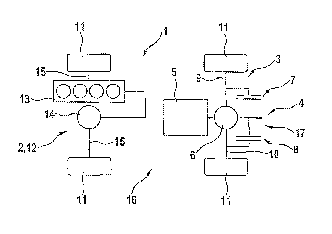
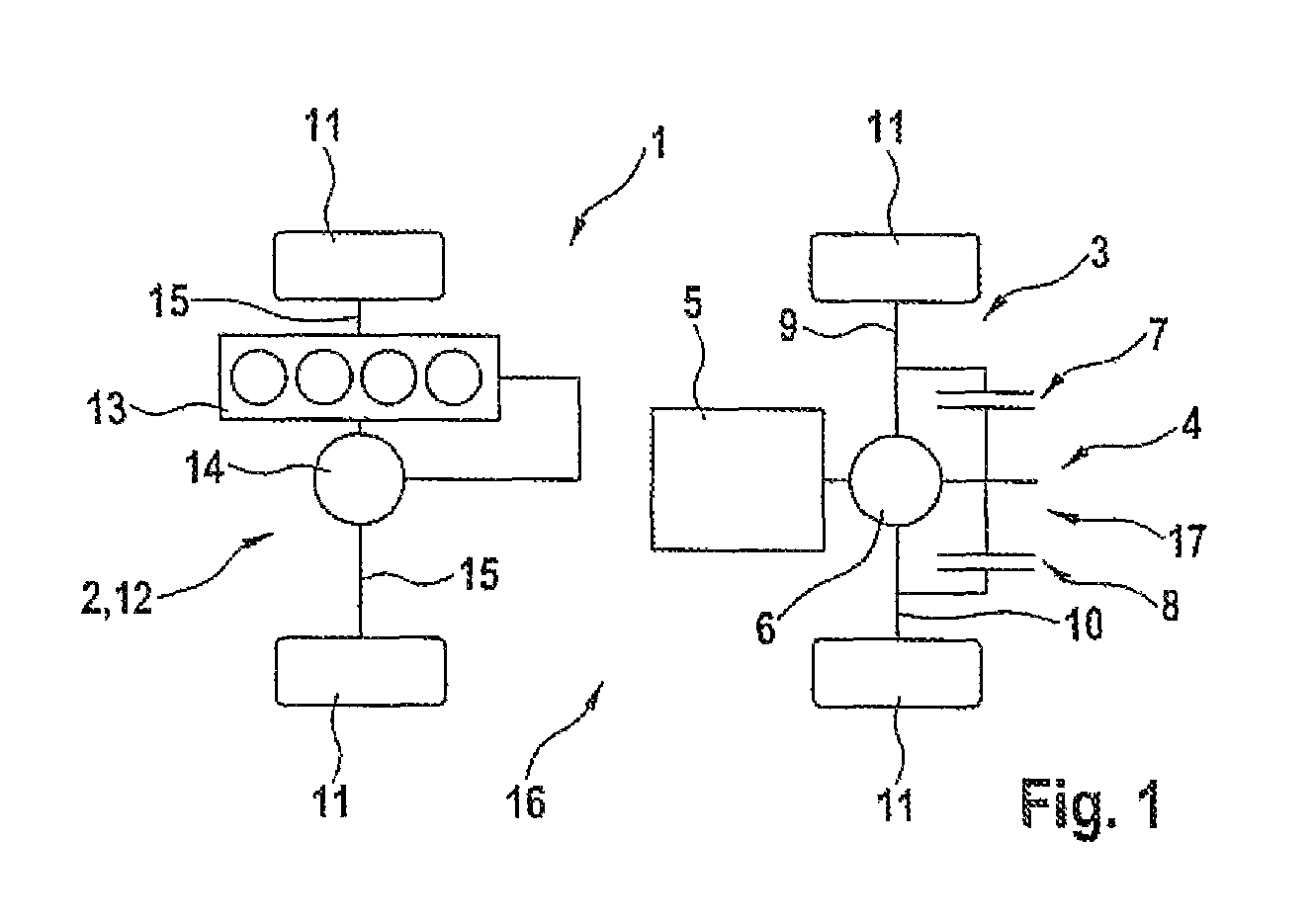
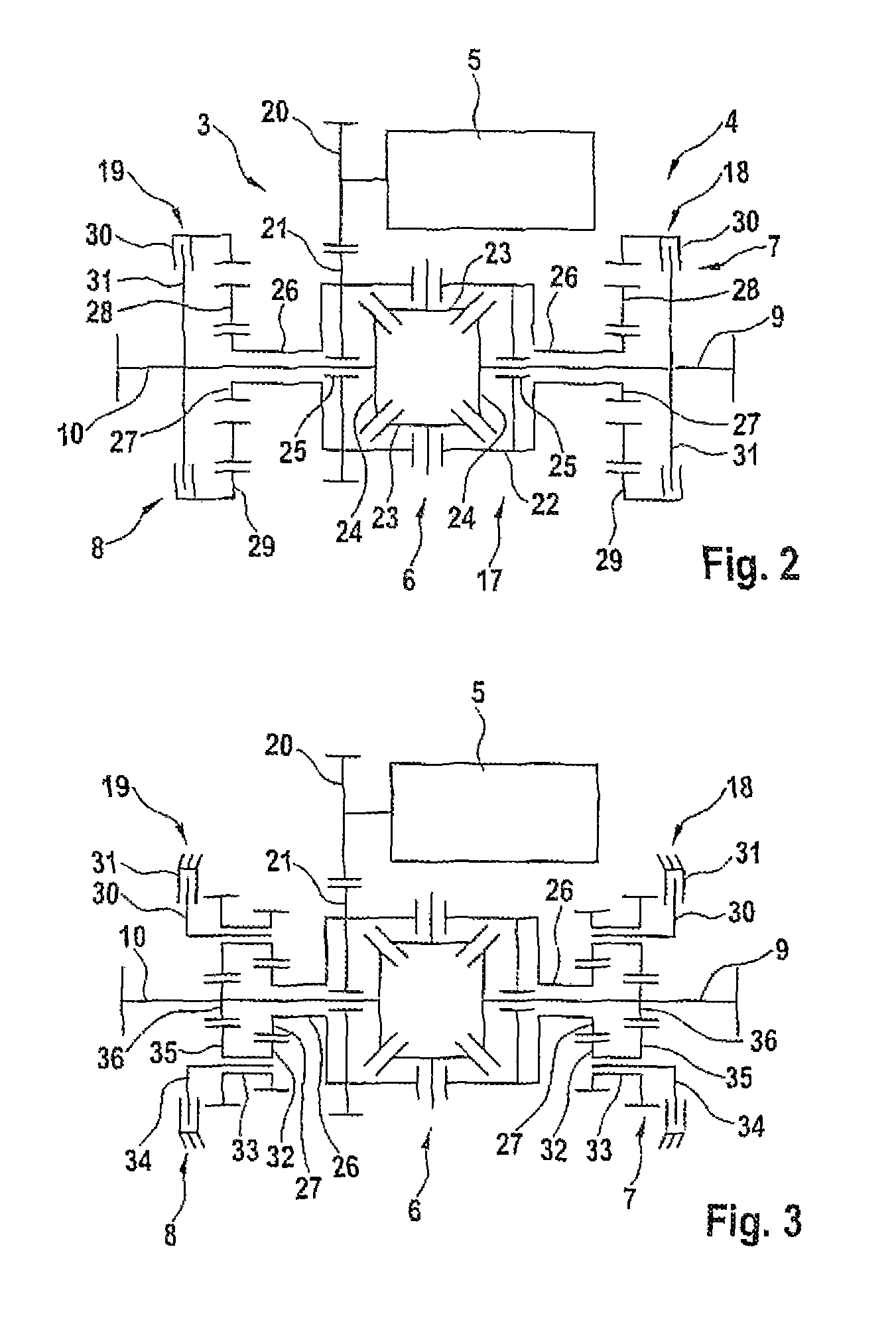
[0024]FIG. 2 shows the axle drive device 4, the rear axle 3 being shown. The drive assembly 5, the differential 6, as well as the first override unit 7, and second override unit 8 are recognizable. The differential 6 with the override units 7 and 8 forms the override differential 17. By way of the override differential 17, the torque produced by the drive assembly 5 is distributed between the first axle section 9 and the second axle section 10. To set the override units 7 and 8, there are a first clutch 18 and a second clutch 19. They can be controlled and / or adjusted independently of one another. In the embodiment shown in FIG. 2, it is provided that by way of the clutches 18 and 19, a torque is applied to the respective axle section 9 or 10 by the respective override unit 7 or 8. The drive assembly 5 is provided axially parallel to the rear axle 3.

[0025]By way of a gear 20, the drive assembly 5 drives a spur gear 21 which is nonrotatably connected to the cage 22 of the differentia...

third embodiment

[0030]FIG. 4 shows the axle drive device 4. The general structure of the illustrated axle drive device 4 corresponds to the one shown in FIGS. 2 and 3. Therefore, reference is made to the corresponding statements and only the differences are described below. The override units 7 and 8 here are not arranged symmetrically around the differential 6, but are located on one side of the differential 6. The manner of action corresponds to that already described. The hollow shaft 26 connected to the differential cage 22 drives a override drive 37 by way of the gear 27. The drive, for this purpose, has a first gear 38 which meshes with the gear 27. The override drive 37 has likewise a second gear 39 and a third gear 40 which are nonrotatably mounted on a common shaft 41 together with the first gear 38. Without actuating the clutch 18 and another clutch 42, symmetrical division of the driving torque between the axle sections 8 and 9 takes place. The gear stages 27 and 38, 39 and 43, as well a...


PUM


Abstract

The invention relates to an axle drive device for an axle of a motor vehicle, with a drive assembly and a differential. Here, it is provided that the drive assembly is in the form of an electrical drive assembly and the differential has at least one override unit. The invention furthermore relates to a motor vehicle.

Description

[0001]The invention relates to an axle drive device for an axle of a motor vehicle, with a drive assembly and a differential. The invention furthermore relates to a motor vehicle.BACKGROUND OF THE INVENTION[0002]Axle drive devices of the initially mentioned type are known from the prior art. In the overwhelming majority of motor vehicles, propulsion according to the current prior art takes place via a drive assembly designed as an internal combustion engine. The driving torque is transferred to the wheels of the motor vehicle by way of a transmission and a differential. For all-wheel drive vehicles the driving torque is divided between the front and rear axles by way of different types of distribution systems. For example, a mid-differential and clutch should be mentioned here. Mechanical all-wheel drive systems, starting, in particular, from vehicles of a certain size class (B segment), generally distribute a high proportion of the driving torque to the rear axle. The objective her...

Claims


Application Information

Patent Timeline
Patent Type & Authority Patents(United States)
IPC IPC(8): F16H48/06F16H48/08F16H48/30F16H48/36
CPCB60K6/387B60K6/48B60K6/52B60W10/06B60W10/08B60W20/00F16H48/30F16H48/36B60L2240/423B60W2540/10B60W2710/0666B60W2710/083F16H48/08F16H2048/366F16H2048/368Y02T10/6221Y02T10/6265Y02T10/6286Y02T10/642F16H2200/0021Y02T10/62Y02T10/64B60W10/14B60W10/02
Inventor STRASSER, SEBASTIANSCHWARZ, RALF
Owner AUDI AG
Why Eureka
Try Eureka