Battery temperature unevenness suppressing power supply

a power supply and temperature suppression technology, applied in the field of batteries, can solve the problems of difficult to evenly cool the batteries, the temperature difference between the batteries will arise, and the performance of the batteries will deteriorate, so as to reduce the cost and the necessary man-hours, secure and stable attachment, and the effect of easy attachment to the battery modul

Active Publication Date: 2013-08-13
SANYO ELECTRIC CO LTD
View PDF12 Cites 14 Cited by
  • Summary
  • Abstract
  • Description
  • Claims
  • Application Information

AI Technical Summary

Benefits of technology

[0025]According to the first aspect of the present invention, since the thermally-insulating member is arranged on a part of a surface of the battery module, for example, in the case where the thermally-insulating member is arranged in proximity to a battery that is likely to be cooled to a relatively lower temperature by the cooling mechanism, it is possible to suppress dissipation of heat generated by this battery. As a result, it is possible to bring this battery to a higher temperature. That is, since this battery is held warm by heat generated by the battery itself, it is possible to suppress unevenness of battery temperatures in the power supply device.
[0035]In the case where a vehicle includes the aforementioned power supply device, it is possible to provide a battery module that can be simply constructed but can reduce the temperature unevenness ΔT in the battery module, thereby increasing the life of the battery module. In addition, since a vehicle that includes the aforementioned power supply device can be flexibly changed in design, this vehicle is suitable for frequent design change.

Problems solved by technology

If the batteries store the generated heat, the batteries will deteriorate in performance.
However, it is difficult to evenly cool the batteries.
The reason is that a battery near the cooling air inlet is cooled by colder air at a higher flow rate and is likely to be over-cooled, while a battery, which is the furthest away from the cooling air inlet, is cooled at a lower flow rate relative to the battery on the cooling air inlet side and is likely to be poorly cooled so that a temperature difference among between the batteries will arise.
For this reason, as the number of batteries increases, it becomes more difficult to evenly cool the batteries, and the temperature difference will increase.
In addition, if a cooling gas or fluid with large thermal capacity is used to increase cooling performance, the temperature difference will increase.
If batteries are unevenly cooled, some of the batteries that are poorly cooled may deteriorate faster so that the lives of some batteries may be reduced.
In addition, this unevenness will increase as the batteries are used over a long period of time.
Also, some of the batteries will be easily overcharged / over-discharged, which in turn accelerates deterioration of some of the batteries.
Consequently, such unevenness may cause life reduction of the power supply device as a whole.
For this reason, in vehicle power supply devices, the deterioration of some batteries results in a problem with the power supply device as a whole, and reduces the entire performance of the power supply device.
However, since the air flow deflecting member requires a shaping process or an attachment process, there is a problem in that productivity will be low.
In addition, since material, shaping and assembling costs are required, there is a problem in that the production cost will be high.
Accordingly, there is a disadvantage in that the effect will be limited that evens the flow rates in the battery module.
For this reason, this battery cooling structure is not suitable for a structure that includes a number of batteries connected to each other.
In addition to this, it will be very difficult to optimize the arrangement, shape and the like of air flow deflecting members.
Also, in the battery cooling structure that includes, instead of the air flow deflecting member that deflects a cooling air flow and is provided on the wall surface of the device box, a driven member that can be driven by an electric motor so that the flow rate of cooling air can be adjusted based on a cooling requirement to reduce the temperature difference, this battery cooling structure will have the aforementioned problems and disadvantages, and additionally will have a possibility that the flowing direction and the flow rate of the cooling air may not be adjusted in the event of electric motor failure or the like.
As a result, there is a problem in that the battery module may be affected as a whole.
In addition, in this cooling structure, since the flow rate is changed based on the battery cooling requirement, there is a disadvantage in that the position and state of a vortex area produced by the air flow deflecting member will change.

Method used


Image

  • Battery temperature unevenness suppressing power supply
  • Battery temperature unevenness suppressing power supply
  • Battery temperature unevenness suppressing power supply

Examples


Embodiment Construction

)

[0046]The following description will describe embodiments according to the present invention with reference to the FIGS. 1 to 9.

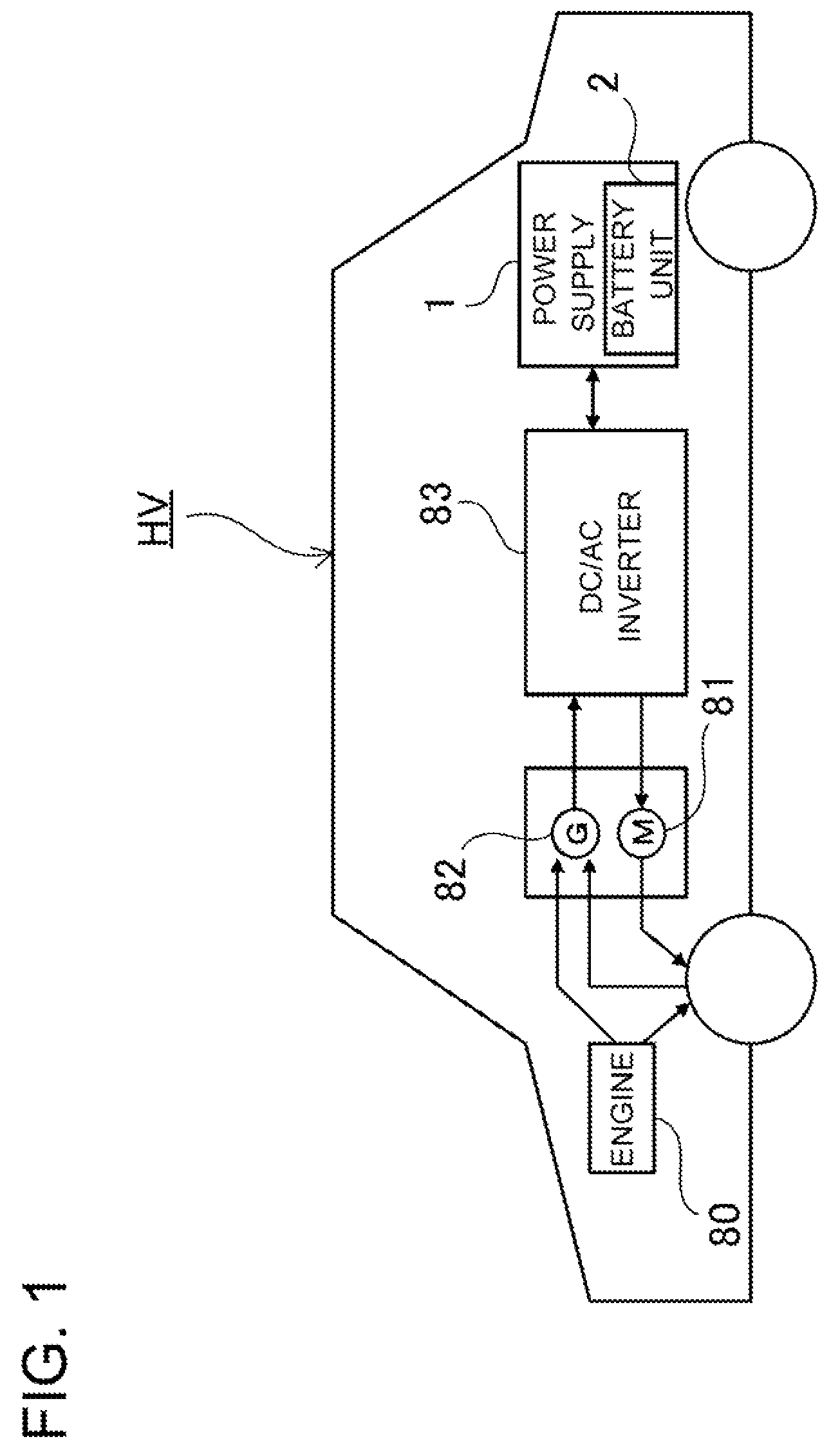
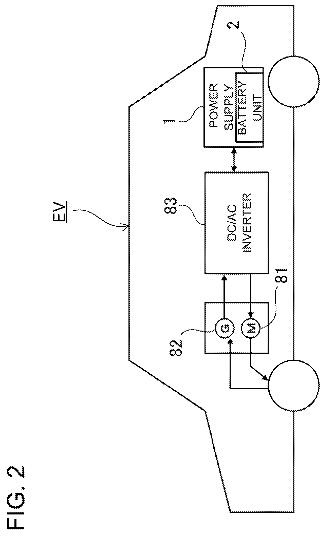
[0047]A power supply device according to the present invention can be installed on electric vehicles such as hybrid cars that are driven by both an engine and a motor, and electric vehicles that are driven only by a motor. The power supply device can be used as a power supply device for these types of vehicles. Exemplary cars including the power supply device are now described with reference to FIGS. 1 and 2.

[0048]FIG. 1 is a block diagram showing an exemplary hybrid car (vehicle HV) that is driven both by an engine 80 and an electric motor 81, and includes a power supply device 1. The illustrated vehicle HV with the power supply device 1 includes the electric motor 81 and the engine 80 that drive the vehicle HV, the power supply device 1 including a battery unit 2 that supplies electric power to the electric motor 81, and an electric generator 82 that cha...


PUM

PropertyMeasurementUnit
thermally-insulatingaaaaaaaaaa
thermally-insulating aaaaaaaaaa
distanceaaaaaaaaaa

Abstract

A power supply device is provided that includes a battery module (3) and a cooling mechanism. The battery module is composed of a plurality of batteries (20) arranged side by side. The cooling mechanism cools the batteries (20). A thermally-insulating member (70) is arranged on a part of a battery module surface, and thermally insulates heat generated from the batteries. This power supply device can reduce the temperature unevenness ΔT.

Description

BACKGROUND OF THE INVENTION[0001]1. Field of the Invention[0002]The present invention relates to a battery module that is composed of a plurality of batteries arranged side by side, and in particular to a power supply device that includes batteries and evens the temperatures of the batteries to be used for electric motors for driving hybrid cars, fuel cars, and electric vehicles.[0003]2. Description of the Related Art[0004]In vehicle power supply devices, a large amount of current is repeatedly charged / discharged. Accordingly, vehicle power supply devices include a plurality of batteries arranged side by side. When vehicles are driven, the batteries generate heat. As a result, the temperatures of batteries will rise. If the batteries store the generated heat, the batteries will deteriorate in performance. For this reason, it is necessary to cool the batteries. In one of methods for cooling batteries, a cooling structure is constructed in such a power supply device, and cooling air i...

Claims


Application Information

Patent Timeline
Patent Type & Authority Patents(United States)
IPC IPC(8): H01M10/50B60L3/00H01M10/60H01M10/613H01M10/617H01M10/625H01M10/647H01M10/651H01M10/652H01M10/6563H01M10/6566H01M10/6568H01M10/658H01M50/209H01M50/224
CPCH01M2/1077H01M10/5004H01M10/5008H01M10/5059H01M10/5032H01M10/5067H01M10/5087H01M10/5016H01M10/625H01M10/6563H01M10/647H01M10/6557H01M10/617H01M10/613H01M10/658Y02E60/10H01M50/209H01M50/224
Inventor SAITO, MASAONAKAMURA, SHINSUKEWAKABAYASHI, AKINOBU
Owner SANYO ELECTRIC CO LTD
Why Eureka
Try Eureka