Wavelength conversion device and related light emitting device

Active Publication Date: 2016-03-10
APPOTRONICS CORP LTD
View PDF4 Cites 15 Cited by
  • Summary
  • Abstract
  • Description
  • Claims
  • Application Information

AI Technical Summary

Benefits of technology

[0017]Compared to conventional technology, embodiments of the present invention have the following advantages:
[0018]In embodiments of the present invention, through the box and the conduit that connects the air inlet and outlet on the box, the wavelength conversion layer is sealed, which prevents duct accumulation affecting the light emitting efficiency of the wavelength conversion material. Further, by using the heat exchanger to lower the air temper

Problems solved by technology

However, because during the excitation process the wavelength conversion efficiency of the particles of wavelength conversion material cannot be 100%, the lost energy becomes heat, causing heat accumulation and rapid temperature increase of the wavelength conversion material particles, directly impacting the light emission efficiency and useful life of the wavelength conversion material.
Thus, in the presence of a large amount of dust and when the light power d

Method used


Image

  • Wavelength conversion device and related light emitting device
  • Wavelength conversion device and related light emitting device
  • Wavelength conversion device and related light emitting device

Examples


Example

First Embodiment

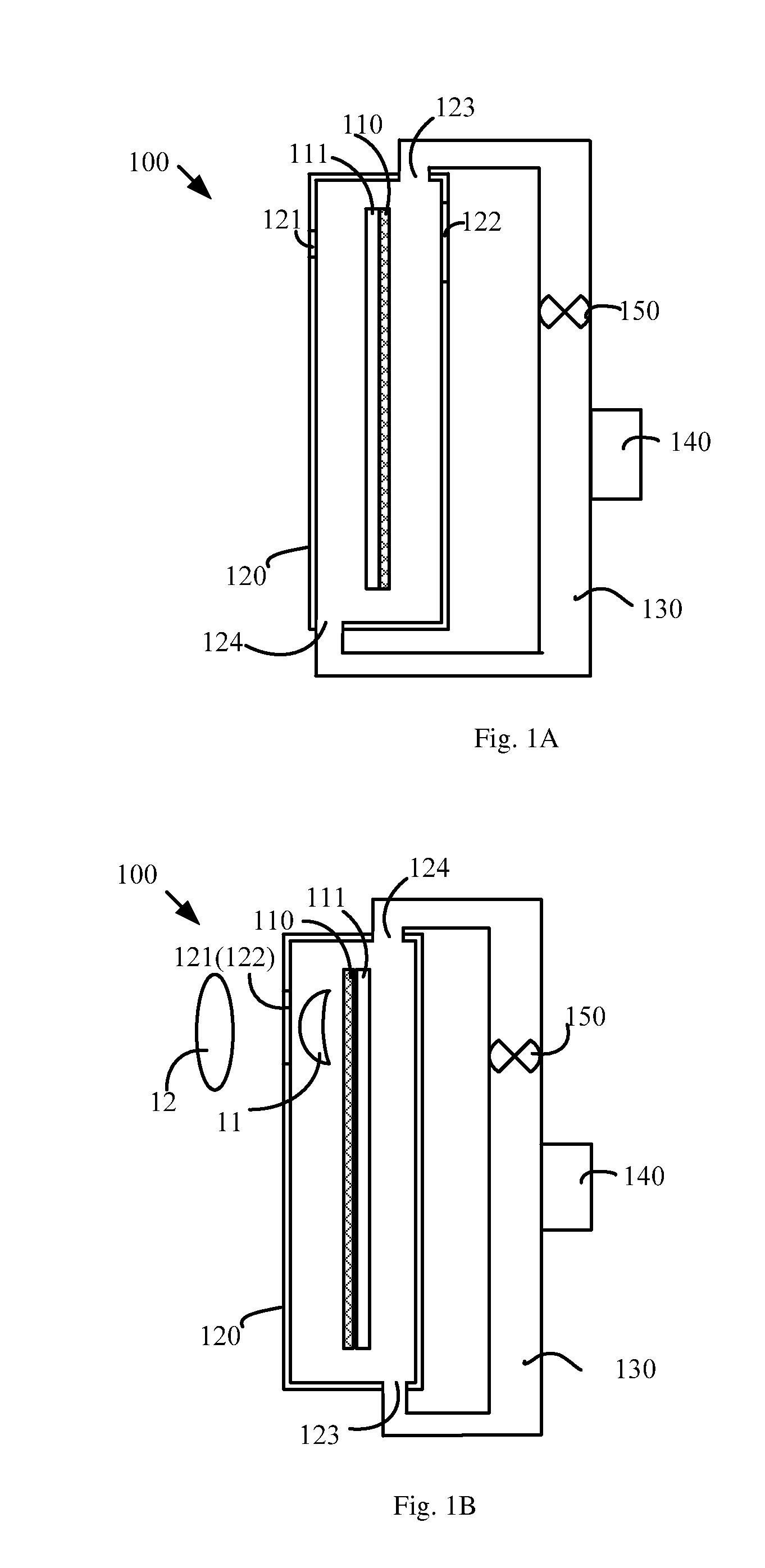
[0035]Referring to FIG. 1, which schematically illustrates the structure of a wavelength conversion device according to an embodiment of the present invention. As shown in FIG. 1, the wavelength conversion device 100 includes a wavelength conversion layer 110, a box 120, a conduit 130, a heat exchanger 140 and an air circulation device 150.

[0036]The wavelength conversion layer 110 is used to absorb an excitation light and generate a converted light. The wavelength conversion layer 110 includes wavelength conversion material. A common wavelength conversion material is phosphor powder, such as YAG (yttrium aluminum garnet) phosphor, which can absorb blue excitation light and generate a yellow converted light. The wavelength conversion material may also be quantum dots, fluorescent dye, and other materials that have wavelength conversion properties, in addition to phosphors. In many situations, the wavelength conversion material is a power or particulate form, and is di...

Example

Second Embodiment

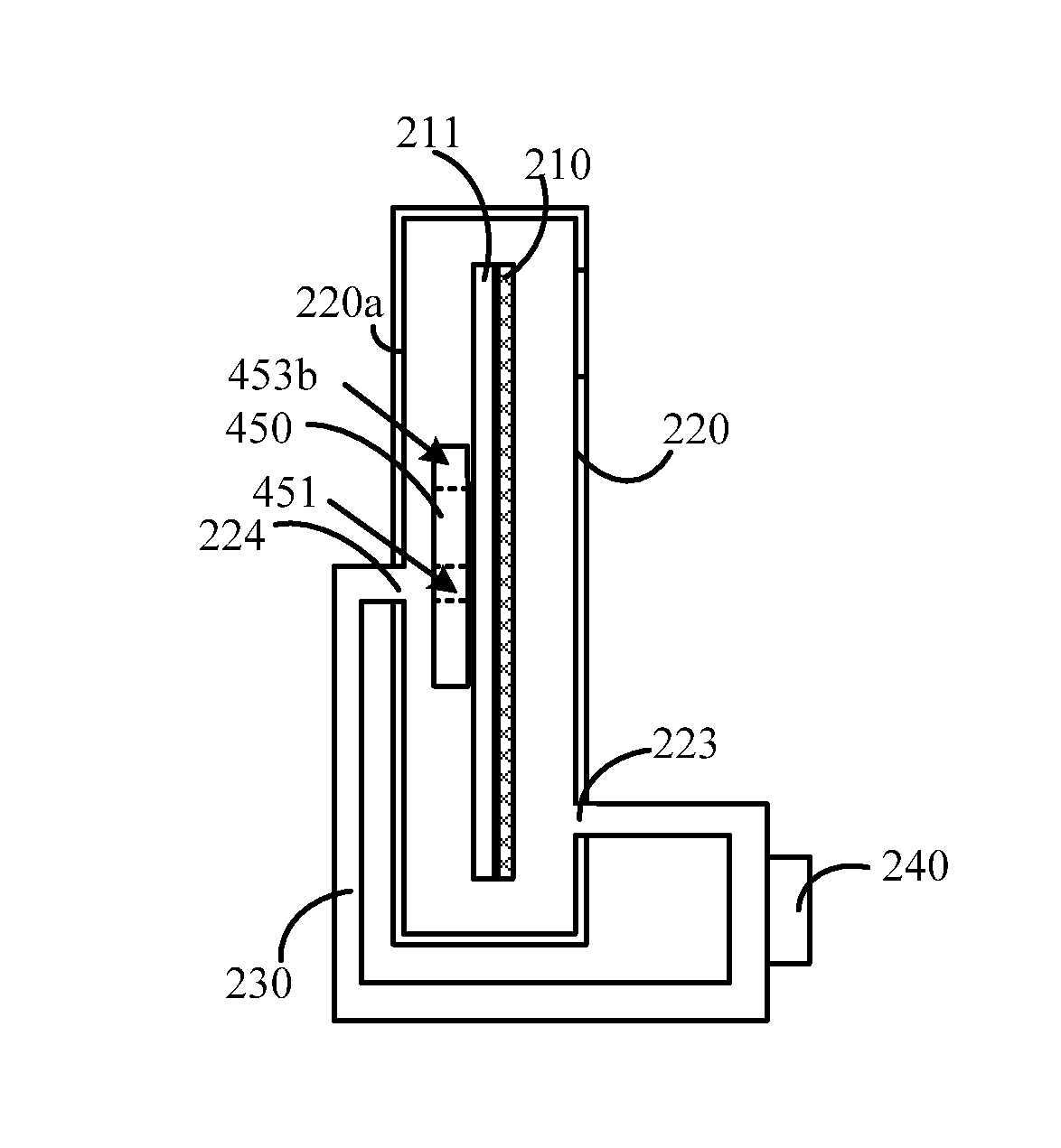
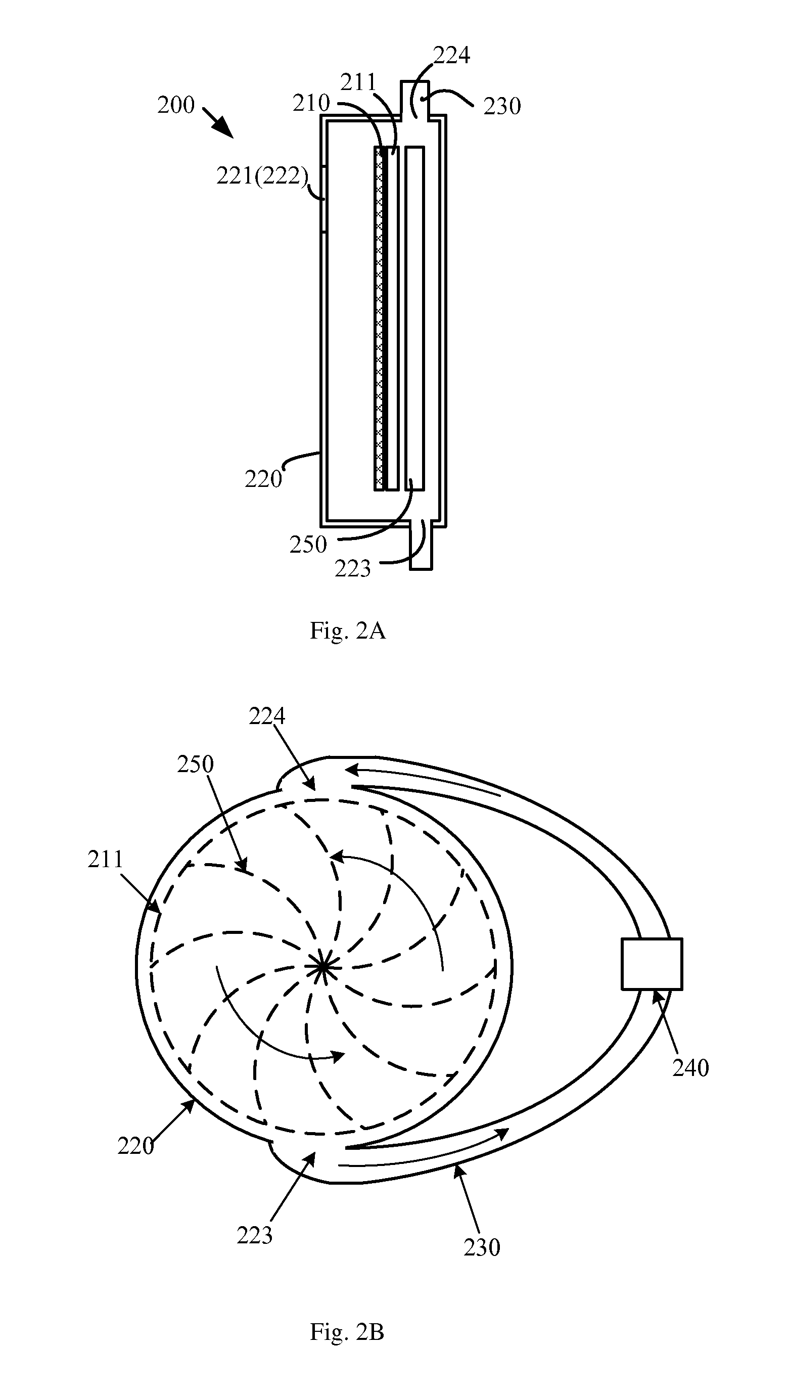
[0056]Refer to FIGS. 2A and 2B, where FIG. 2A schematically illustrates the structure of a wavelength conversion device according to another embodiment of the present invention, and FIG. 2B is a right side view of the wavelength conversion device shown in FIG. 2A. The wavelength conversion device 200 includes a wavelength conversion layer 210, a substrate 211, a box 220, a conduit 230, a heat exchanger 240, and an air circulation device 250. The box 220 includes a first area 221, a second area 222, an air outlet 223, and an air inlet 224.

[0057]Differences between this embodiment and the embodiment of FIG. 1A include:

[0058]In this embodiment, the air circulation device 250 is placed inside the box 220, and located on the side of the substrate 211 that faces away from the wavelength conversion layer 210. Correspondingly, the air outlet 223 and / or the air inlet 224 of the box 220 is located on the side of the plane of the substrate 211 that faces away from the waveleng...

Example

Third Embodiment

[0084]Refer to FIG. 6, which schematically illustrates the structure of a wavelength conversion device according to another embodiment of the present invention. As shown in FIG. 6, the wavelength conversion device 600 includes a wavelength conversion layer 610, a substrate 611, a box 620, a conduit 630, a heat exchanger 640, an air circulation device 650, and a drive device 660. The box 620 includes a first area 621, a second area 622, an air outlet 623 and an air inlet 624.

[0085]Differences between this embodiment and the above embodiments include:

[0086]In this embodiment, the wavelength conversion device 600 further includes a drive device 660 (such as a motor), fixedly coupled to the substrate 611, to drive the wavelength conversion layer 610 to rotate periodically. The surface of the drive device 660 that faces away from the substrate 611 is fixedly connected to the inner surface of the box 620. The substrate 611 is preferably round plate, with at least two segme...


PUM


Abstract

Disclosed are a wavelength conversion device and a light emitting device. The wavelength conversion device includes a wavelength conversion layer used for absorbing excitation light and generating converted light; a box having a first area used for transmitting the excitation light to the wavelength conversion layer and a second area used for transmitting the converted light, and further including an air outlet and an air inlet; a conduit, disposed outside the box and used for connecting the air inlet and the air outlet, so as to seal with the box the wavelength conversion layer in the box; a heat exchanger, used for decreasing a gas temperature in the conduit; and a gas circulation device, disposed in sealed space encircled by the box and the pipe conduit, and used for driving exchange between gas in the box and gas in the conduit. The wavelength conversion device achieves both dust prevention and heat dissipation.

Description

BACKGROUND OF THE INVENTION[0001]1. Field of the Invention[0002]This invention relates to illumination and display fields, and in particular, it relates to a wavelength conversion device and related light emitting device.[0003]2. Description of Related Art[0004]In conventional illumination system or projection system, the light emitting device often employs an excitation light to excite a wavelength conversion material in a wavelength conversion layer to generate a converted light. However, because during the excitation process the wavelength conversion efficiency of the particles of wavelength conversion material cannot be 100%, the lost energy becomes heat, causing heat accumulation and rapid temperature increase of the wavelength conversion material particles, directly impacting the light emission efficiency and useful life of the wavelength conversion material.[0005]A common solution for this problem is that, by using a drive device to drive the wavelength conversion layer to mo...

Claims


Application Information

Patent Timeline
IPC IPC(8): F21V29/65F21K2/00F21V9/40
CPCF21K2/00F21V29/65G02B7/008G02B26/008G02F1/1336G02F2201/36G03B21/16G03B21/204G02F1/133614G02F1/133628
Inventor HU, FEITIAN, ZIFENGYANG, YIFU, WEI
Owner APPOTRONICS CORP LTD
Why Eureka
Try Eureka