Gas turbine having water injection unit

a technology of gas turbine and water injection unit, which is applied in the ignition of turbine/propulsion engine, combustion air/fuel air treatment, engine starters, etc., can solve the problems of not teaching nor suggesting water injection into the compressor itself, and achieve the effect of lowering the temperature of the air

Inactive Publication Date: 2006-05-09
HITACHI LTD
View PDF21 Cites 58 Cited by
  • Summary
  • Abstract
  • Description
  • Claims
  • Application Information

AI Technical Summary

Benefits of technology

[0118]Further, if it is accepted that there may be some cases wherein the above-mentioned operation and effect are not sufficiently presented, instead of the above-mentioned injection unit, arranged within an intake air duct at an upstream side of the compressor and constructed so that water droplets are injected into the air to be supplied to the compressor to lower the temperature of the air to be supplied into the compressor than an atmospheric temperature and the sprayed water droplets introduced into the compressor with the air having lowered in temperature are evaporated during passage through the compressors or in addition to the above-mentioned injection unit, the above-mentioned control unit can be employed for a system or apparatus provided with a cooling device for cooling air supplied to the compressor to increase output. The cooling device can be a device for effecting direct or indirect heat exchange with air supplied to the infection unit and the compressor, using a cold heat source such as ice, liquid air, etc.

Problems solved by technology

However, this control does not teach nor suggest water injection into the compressor itself, and is not concerned with control of humidity at the inlet of the compressor.

Method used


Image

  • Gas turbine having water injection unit
  • Gas turbine having water injection unit
  • Gas turbine having water injection unit

Examples


first embodiment

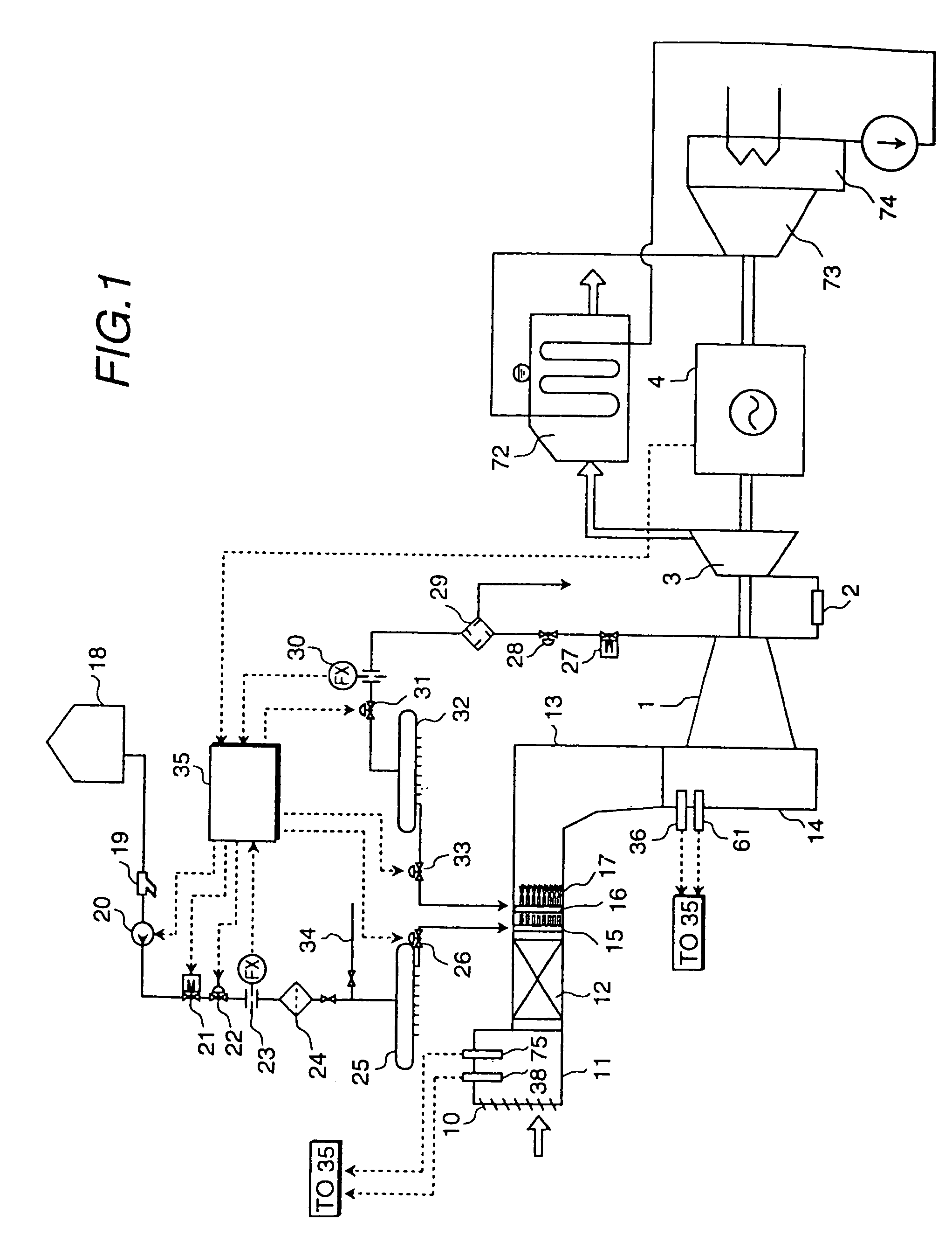
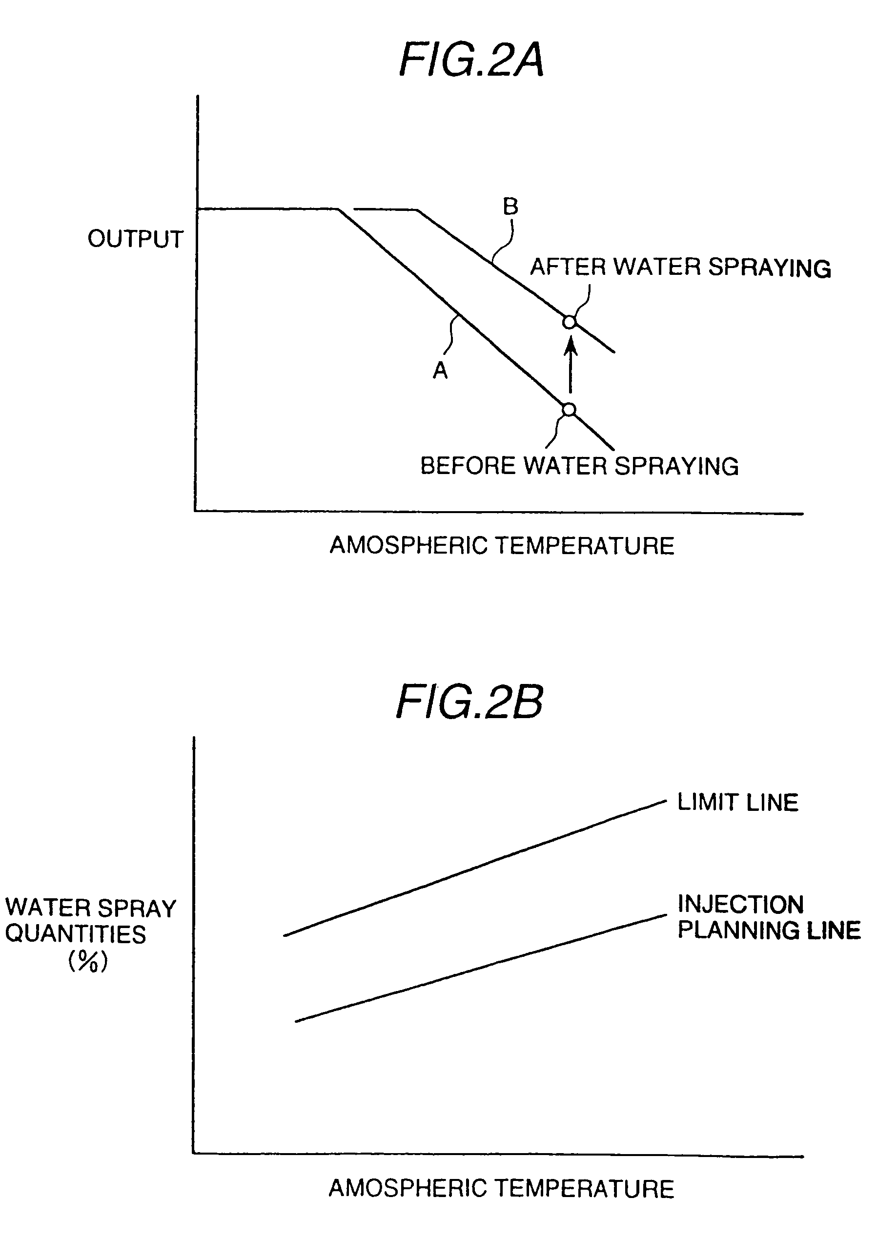
[0148]the invention will be described with reference to FIGS. 1 and 2A and 2B.

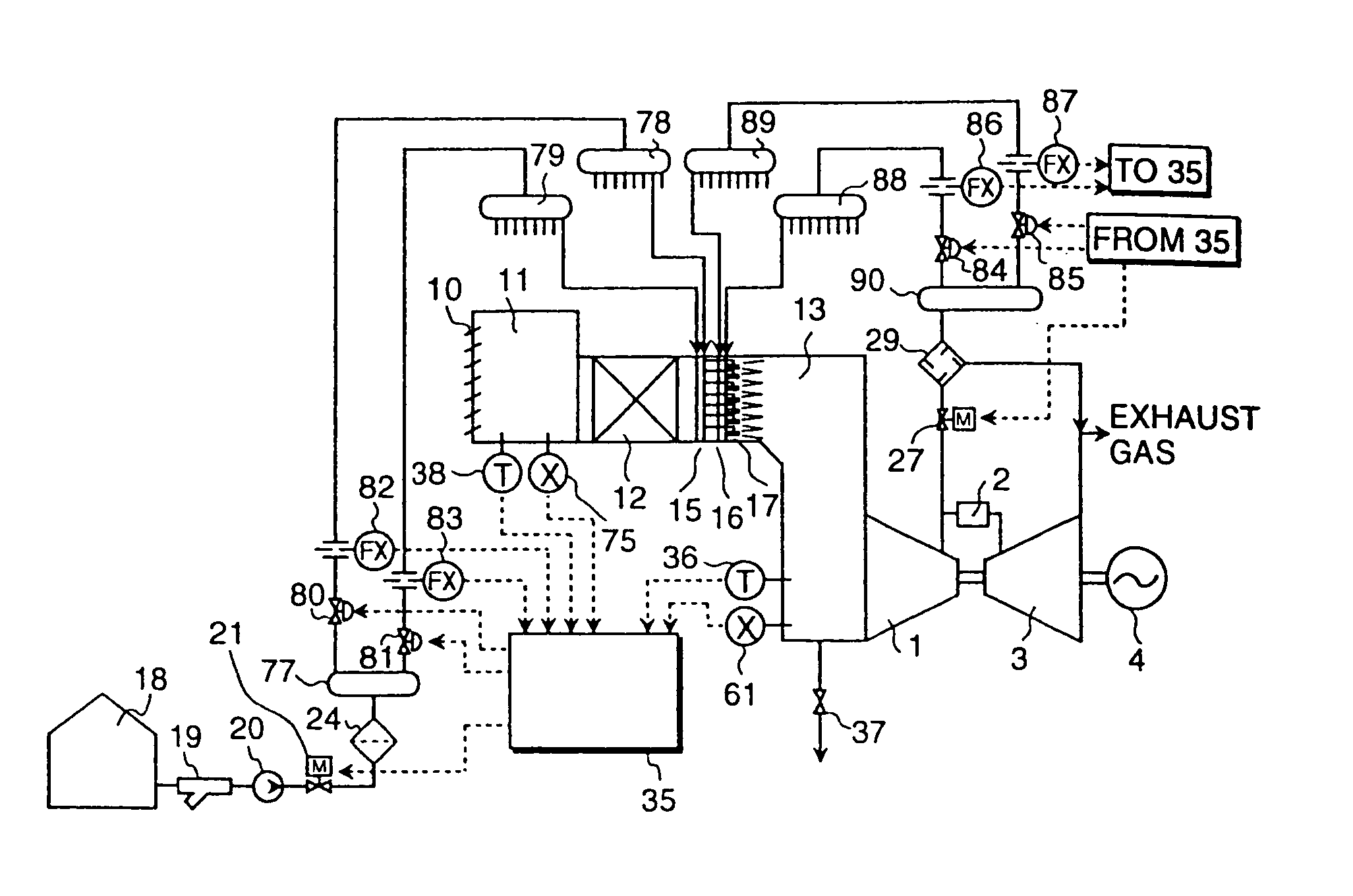
[0149]A gas turbine according to this embodiment of the invention as indicated in FIG. 1 comprises a compressor 1 which compresses and discharges a gas, a combustor 2 to which the gas compressed by the compressor is supplied, a turbine 3 which is driven by a combustion gas of the combustor 2, and a generator 4 which is connected to the shaft of the turbine 3. A gas turbine exhaust gas is introduced into an exhaust heat recovery boiler 72 for heat exchange with a steam or water which becomes a working medium to drive a steam turbine 73, then it is discharged to the atmosphere. The steam turbine 73 which is driven by the steam which is heated through the heat exchange with the gas turbine exhaust gas is directly coupled with the generator 4. A steam discharged from the steam turbine 73 is cooled by a condenser 74 to be condensed into water. An air suction chamber 11 takes in air to be supplied to the compres...

second embodiment

[0183]the invention will be described with reference to FIGS. 1 and 3.

[0184]In the second embodiment, a water spray quantity is controlled according to an opening of inlet guide vanes of the compressor 1. Concretely, a water spray quantity is made more when the compressor inlet guide vane opening is larger than when small.

[0185]The present embodiment has basically the same construction as the first embodiment. The second embodiment is provided with a control unit in which signals of opening of the compressor inlet guide vanes are inputted in the control unit 35 and a water spray quantity is controlled according to the signals, in addition to the construction of the first embodiment.

[0186]FIG. 3 shows planning lines for water injection (spray) quantities controlled according to atmospheric temperatures, in which its water spray quantity is controlled so as to differ according to openings of the inlet guide vanes of the compressor.

[0187]In this embodiment, its water spray injection is...

third embodiment

[0192]the present invention will be described hereunder, referring to FIGS. 1, 2A, 2B, 4, 5A, 5B and 6.

[0193]In the present embodiment, a water spray quantity from the spray nozzle 17 is controlled on the basis of the atmospheric temperature and humidity. Concretely, a water spray quantity is made more when the atmospheric temperature is higher than when low and the water spray quantity is made larger when the humidity is lower than when high.

[0194]The present embodiment has basically the same construction as the first embodiment. The present embodiment is provided with a temperature detecting device 38 and humidity detecting device 75 at the upstream side of the spray nozzle 17, for example within the intake chamber 11, in addition to the construction of the first embodiment. Signals from the detectors are input in the control unit 35 and a water spray quantity of the water spray nozzle 17 is controlled according to the signals. FIG. 4 indicates a water spray quantity limit line wi...


PUM


Abstract

A gas turbine comprises a compressor for compressing a gas supplied therein and discharging the compressed gas, a combustor in which the discharged gas from the compressor and a fuel are combusted, a turbine to be driven by a combustion gas from the combustor, and a water injection unit which injects water into the gas to be supplied to the compressor, thereby lowering the temperature of the gas to be introduced into the compressor to a temperature lower than the atmospheric temperature, and causing water droplets having been injected in the gas and within the compressor to be vaporized while flowing down therein, wherein the quantity of water spray injection is controlled while monitoring operational conditions of the gas turbine.

Description

[0001]This is a divisional application of U.S. Ser. No. 10 / 704,842, filed Nov. 12, 2003, now U.S. Pat. No. 6,779,332; which is a divisional application of U.S. Ser. No. 10 / 244,410, filed Sep. 17, 2002, now U.S. Pat. No. 6,705,074; which is a divisional application of U.S. Ser. No. 10 / 156,949, filed May 30, 2002, now U.S. Pat. No. 6,530,210; which is a divisional application of U.S. Ser. No. 09 / 855,678, filed May 16, 2001, now U.S. Pat. No. 6,711,888; which is a divisional application of U.S. Ser. No. 09 / 106,077, filed Jun. 29, 1998, now U.S. Pat. No. 6,260,350.BACKGROUND OF THE INVENTION[0002]A conventional gas turbine is caused to drop its output in a summer season when the temperature increases, therefore, various arrangements have been proposed as a method to recover the dropped output.[0003]JP-A Laid-Open No. 7-97933, JU No. 61-37794, or JP-A Laid-Open No. 5-195809 disclose that the intake air of the compressor is cooled.[0004]Further, JP-A Laid-Open No. 61-283723 discloses that...

Claims


Application Information

Patent Timeline
Patent Type & Authority Patents(United States)
IPC IPC(8): F02C7/00F02C7/143F02G3/00
CPCF02C7/1435Y02E20/16F02C7/04
Inventor HORII, NOBUYUKITAKEHARA, ISAOMURATA, HIDETAROUTAMURA, MOTOAKIKUWAHARA, TAKAAKISASADA, TETSUOHIROSE, FUMIYUKIKATOH, YASUHIRO
Owner HITACHI LTD
Why Eureka
Try Eureka