Semiconductor device having a fuse and a low heat conductive section for blowout of fuse

a technology of a fuse and a low heat conductive section, which is applied in the field of fuse, can solve the problems of insufficient heat supplied by the laser beam, insufficient heat supplied by the fuse, and insufficient heat to blow the fus

Inactive Publication Date: 2005-12-06
RENESAS ELECTRONICS CORP
View PDF11 Cites 14 Cited by
  • Summary
  • Abstract
  • Description
  • Claims
  • Application Information

AI Technical Summary

Benefits of technology

[0017]In light of the above problems, an object of the present invention is to suppress the heat dissipation which may take place through the heat conduction along the fuse and the interconnection(s), and to attain good thermal storage at the irradiation site of the laser beam, and thereby to achieve a complete disconnection of the fuse.
[0019]Further, the present invention provides a blowout method of a fuse through the use of a laser beam, a fuse making connection between one end of a first interconnection and one end of a second interconnection, wherein the other end of said first interconnection is connected to a low heat-conductive section which has a lower heat conductivity than said first interconnection and thereby a heat generated at a laser beam irradiation site is prevented from being conducted further beyond said low heat-conductive section.
[0022]When the fuse is blown by the irradiation of a laser beam as described above, some of the heat supplied by the laser bean may dissipate, being conducted along the fuse and the first interconnection. Yet, because the first interconnection is connected to a first low heat-conductive section having a heat conductivity lower than that of the first interconnection, the heat is prevented from being conducted further beyond the first low heat-conductive section. As a result, the heat is stored at the laser beam irradiation site and the complete blowout of the fuse may be achieved.
[0023]Accordingly, the present invention can replace faulty cells with redundancy cells, for certain, through blowout of the fuse, which is made by the laser beam irradiation. Further, the present invention can disconnect, for certain, the test cell and the likes from the memory cell(s), the logic cell(s) and the likes.
[0024]As set forth above, in a semiconductor device comprising a fuse which makes connection between a first interconnection and a second interconnection, and a first low heat-conductive section which makes connection between the first interconnection and a third interconnection at a site of the first interconnection where the fuse is not connected, the first low heat-conductive section is fabricated from a material having a heat conductivity lower than that of the material to form the first interconnection, whereby, in making the fuse blown with the laser beam irradiation, the heat dissipation through the heat conduction along the fuse and the interconnection is well suppressed, and, therefore, the disconnection at the fuse can be achieved, satisfactorily.

Problems solved by technology

Nevertheless, when a conventional through-hole type fuse is to be blown by a laser beam, the heat supplied by the laser beam may become insufficient due to the heat dissipation, with some of the heat being conducted along the interconnection(s), so that the complete blowout of the fuse may not be achieved.
Consequently, the heat to blow the fuse may become insufficient and, in some cases, a fuse residue 123 becomes liable to remain, as shown in FIG. 12(c), and the disconnection, faulty.
Moreover, although the value of resistance for this fuse residue is several ten times—one hundred times as much as the value of resistance for the original fuse prior to the laser beam irradiation, it may be still insufficient to activate the test cell or the redundancy cells.
The faulty disconnection of this sort is apt to happen particularly when the interconnection is formed from the material with a high heat conductivity such as Al or Cu, since such an interconnection makes the heat conduct very rapidly to the dissipation.
Especially when the length of the horizontal type fuse is set small for the sake of miniaturization of the semiconductor device, the heat supplied by the laser beam irradiating the fuse does not stay within the fuse but spreads over, being conducted along the interconnections, so that faulty disconnection is very much liable to happen.

Method used


Image

  • Semiconductor device having a fuse and a low heat conductive section for blowout of fuse
  • Semiconductor device having a fuse and a low heat conductive section for blowout of fuse
  • Semiconductor device having a fuse and a low heat conductive section for blowout of fuse

Examples


Embodiment Construction

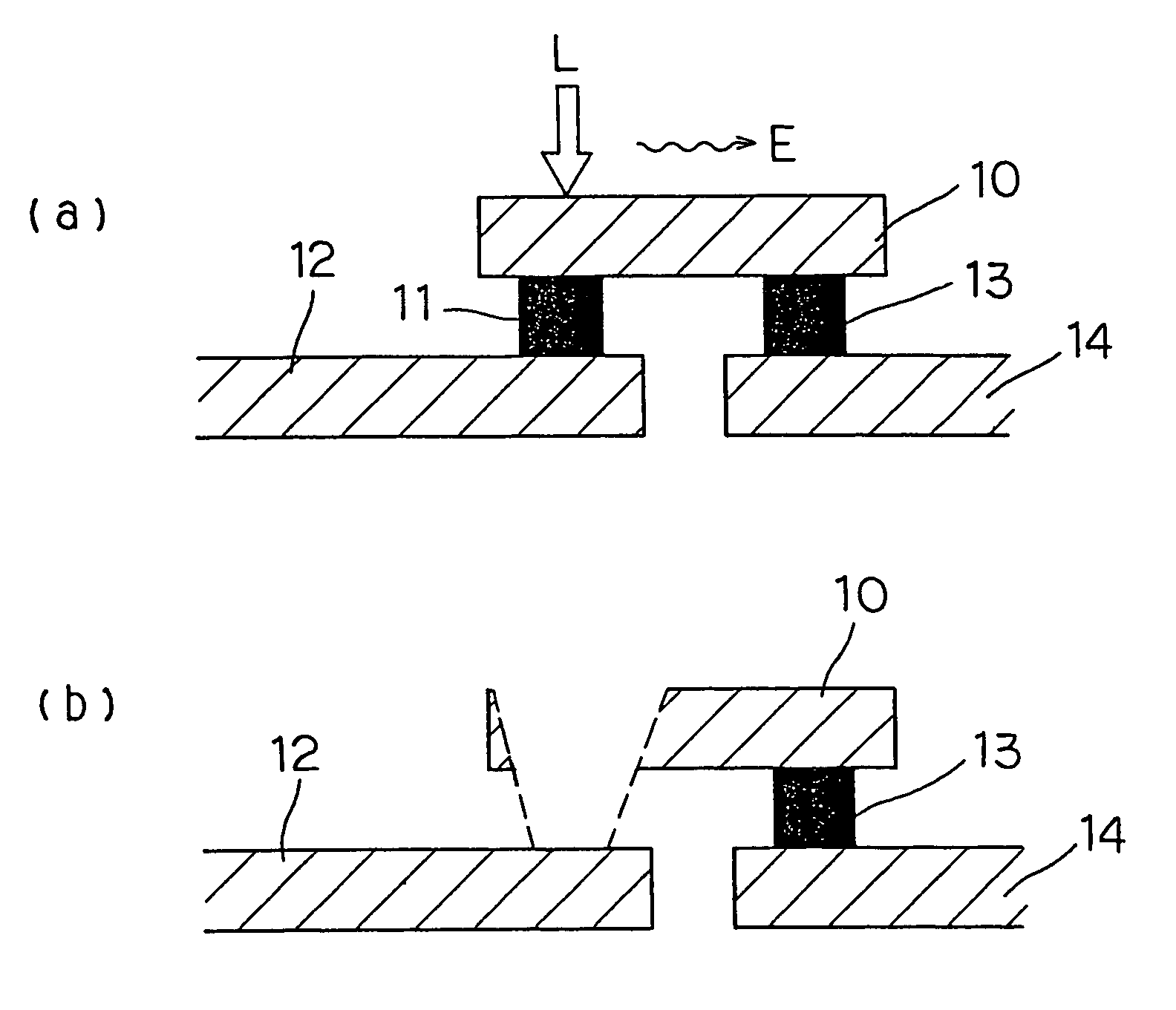
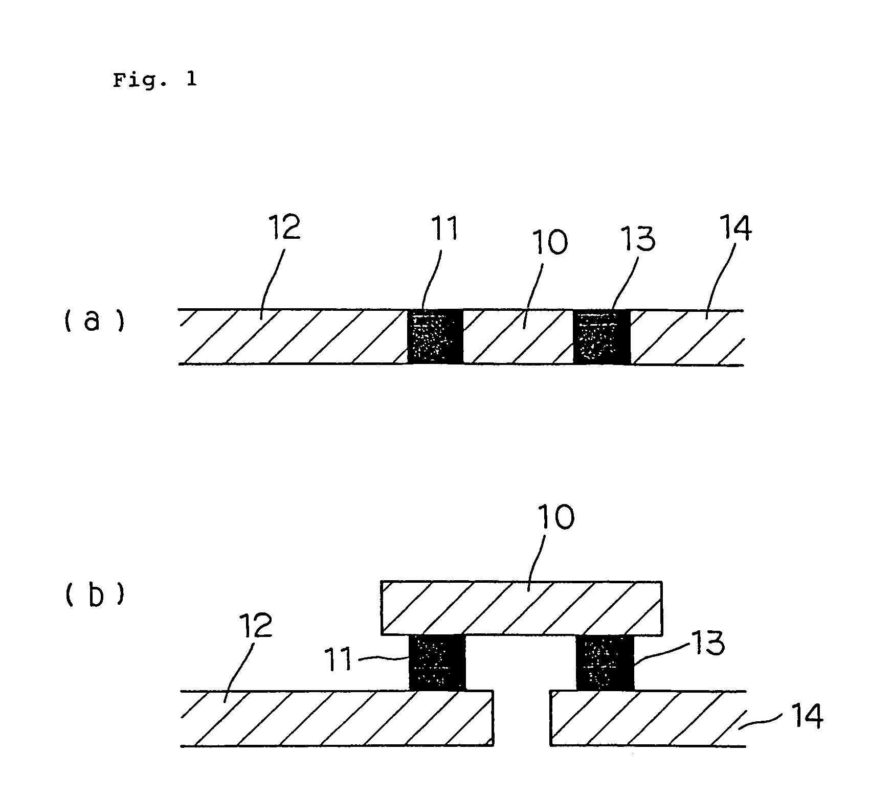
[0039]In FIG. 1, there are shown a plan view (a) and a cross-sectional view (b) of one example of a semiconductor device structure, in the case that the fuse 11 and the first low heat-conductive section 13 are vertical type. In this case, the first interconnection 10 and the second interconnection 12 are connected to each other through the fuse 11, and at a site of the first interconnection 10 where the fuse is not connected, the first interconnection 10 and the third interconnection 14 are connected to each other through the first low heat-conductive section 13. In addition, the first low heat-conductive section 13 is formed from a material having a heat conductivity lower than that of the material to form the first interconnection 10.

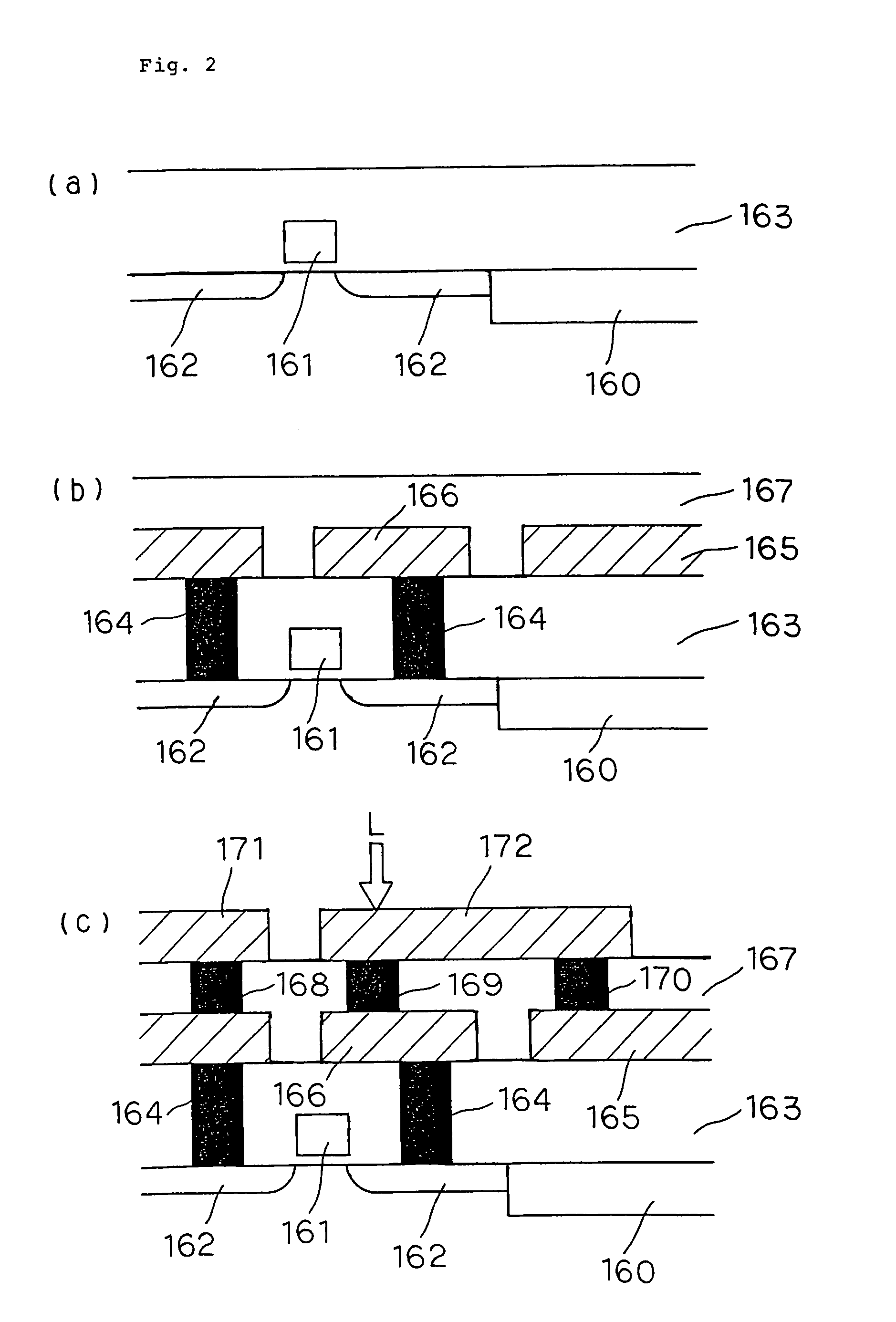
[0040]More specifically, this first example of a semiconductor device has a multi-layered interconnection structure as shown in FIG. 2(c), comprising a fuse 169 which is formed by filling up, with a buried material, a through hole formed to run throug...


PUM


Abstract

In a semiconductor device having a fuse 11 which makes connection between a first interconnection 10 and a second interconnection 12, and a first low heat-conductive section 13 which makes connection between the first interconnection 10 and a third interconnection 14 at a site of the first interconnection 10 where the fuse 11 is not connected, the first low heat-conductive section 13 is fabricated from a material having a heat conductivity lower than that of the material to form the first interconnection 10. When the fuse is blown with the laser beam irradiation, the heat dissipation through the heat conduction along the fuse and the interconnection is to be suppressed, and thereby a satisfactory disconnection at the fuse is to be achieved.

Description

CROSS-REFERENCE TO RELATED APPLICATION[0001]This application is a continuation of application Ser. No. 10 / 780,315, filed on Feb. 17, 2004, abandoned, which is a continuation of application Ser. No. 10 / 136,980, filed on May 1, 2002, abandoned, both of which applications are hereby incorporated herein by reference.BACKGROUND OF THE INVENTION[0002]The present invention relates to a fuse for altering the circuit network in a semiconductor device.[0003]The semiconductor device, in general, comprises the test cell for checking the quality of the chips as well as the redundancy cells for replacing faulty cells, if found. The connection and disconnection of the test cell and the redundancy cells are made through disconnection at the fuse(s) which are formed in the semiconductor device, altering the circuit network therein. The disconnection at a fuse (referred to as the blowout of a fuse, hereinafter) is carried out by applying a laser beam onto the fuse or the vicinity of the fuse.[0004]FI...

Claims


Application Information

Patent Timeline
Patent Type & Authority Patents(United States)
IPC IPC(8): H01L23/525
CPCH01L23/5258H01L2924/0002H01L2924/00
Inventor HASHIMOTO, SHINGO
Owner RENESAS ELECTRONICS CORP
Why Eureka
Try Eureka