Electric power steering system

a technology of electric power steering and steering shaft, which is applied in the direction of steering initiation, instrumentation, vessel construction, etc., can solve the problems of recognition of abnormal computation of overheat protection, and achieve the effect of suppressing heat dissipation and reducing the effort of the driver

Active Publication Date: 2012-04-26
MITSUBISHI ELECTRIC CORP
View PDF2 Cites 14 Cited by
  • Summary
  • Abstract
  • Description
  • Claims
  • Application Information

AI Technical Summary

Benefits of technology

[0012]An electric power steering system in accordance with the present invention includes a motor that is driven based on a target current value computed in line with a steering wheel torque exerted by a driver, and alleviates a driver's steering effort using an assistant torque generated by the motor. The electric power steering system includes an overheat protection current value arithmetic unit that computes an overheat protection current value to which a current flowing into the motor is limited, and an overheat protection control unit that limits the current, which flows into the motor, on the basis of the computed overheat protection current value, suppresses heat dissipation caused by the current flowing into the motor, and protects onboard equipment. The electric power steering system is characterized in that: the computed overheat protection current value or information relevant to the overheat protection current value is stored; and whether a newly computed overheat protection current is abnormal is decided based on comparison of the newly computed overheat protection current value with the stored information relevant to the overheat protection current value.

Problems solved by technology

If a difference between a result of new computation for overheat protection and a result of previous computation for overheat protection exceeds a predetermined value, an abnormality in computation for overheat protection is recognized.

Method used


Image

  • Electric power steering system
  • Electric power steering system
  • Electric power steering system

Examples


embodiment 1

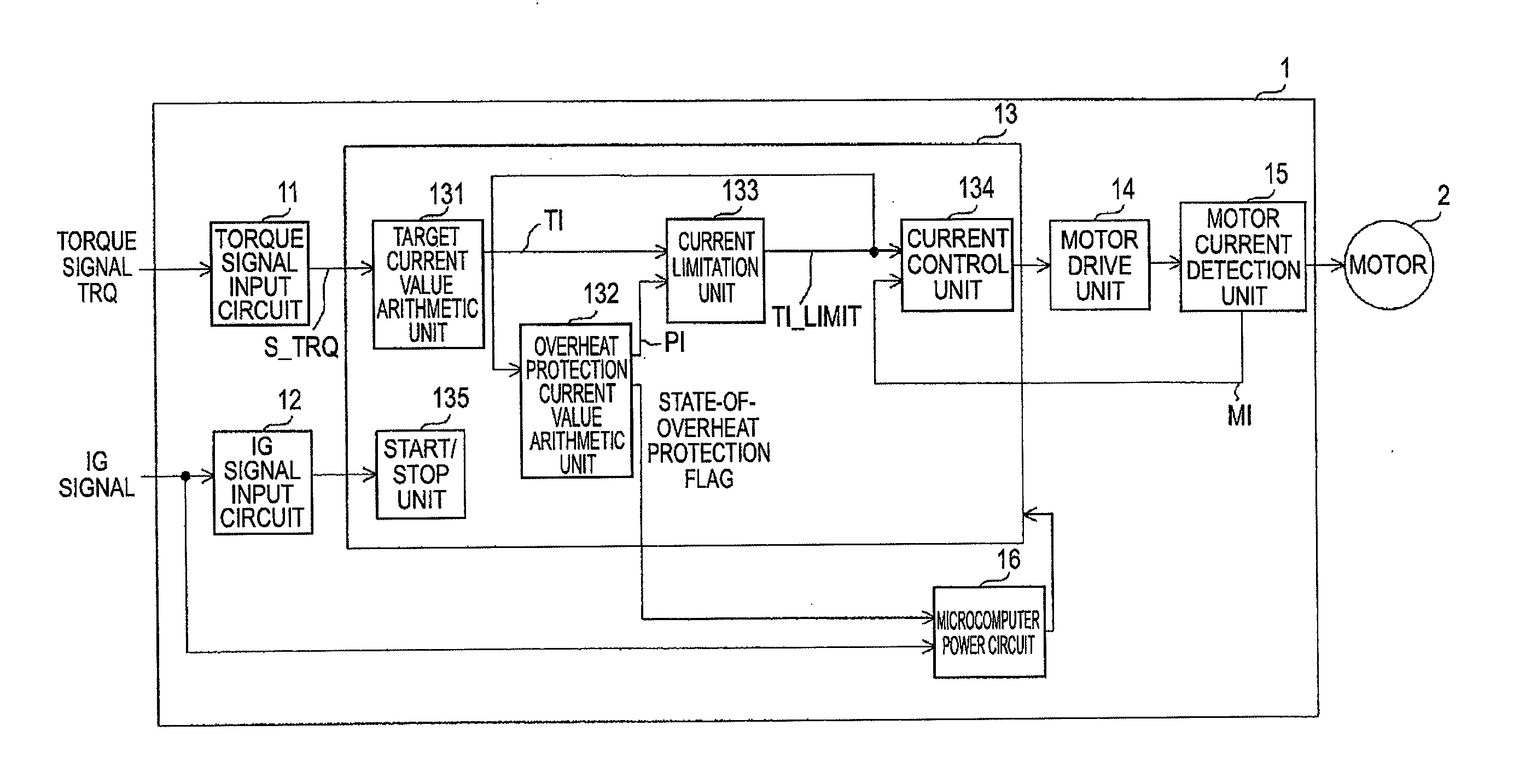
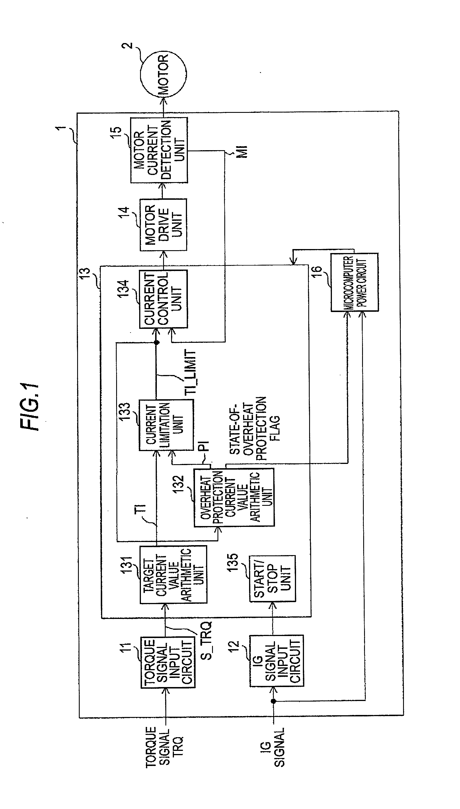
[0027]Referring to the drawings, an electric power steering system in accordance with an embodiment 1 of the present invention will be described below. FIG. 1 is a control block diagram of the electric power steering system in accordance with the embodiment 1 of the present invention. In FIG. 1, an ECU 1 is a control unit that drives or controls a motor 2, which applies an assistant torque to a steering shaft (not shown), on the basis of a signal sent from a vehicle such as a torque signal sent from a torque sensor (not shown) which measures a steering wheel torque exerted by a driver, or an IG signal representing a state of connection of an ignition switch (not shown).

[0028]The ECU 1 includes a torque signal input circuit 11, an IG signal input circuit 12, a microcomputer 13, a motor drive unit 14, a motor current detection unit 15, and a microcomputer power circuit 16. In the microcomputer 13, a target current value arithmetic unit 131, an overheat protection current value arithme...

embodiment 2

[0074]Next, an electric power steering system in accordance with an embodiment 2 of the present invention will be described below. In the foregoing embodiment 1, if a decision is made that an abnormality has occurred in computation of an overheat protection current value, processing such as lighting of a warming lamp is carried out. The electric power steering system in accordance with the embodiment 2 calculates an overheat protection current value on the basis of information relevant to a previously computed overheat protection current value, and uses the calculated value as a new overheat protection current value.

[0075]FIG. 9 is a flowchart concerning an overheat protection current value arithmetic unit included in the electric power steering system in accordance with the embodiment 2 of the present invention. The flowchart shown in FIG. 9 is what is obtained by changing step S8 in the flowchart concerning the embodiment 1 shown in FIG. 3 into step S81. The other steps are identi...

embodiment 3

[0082]Next, an electric power steering system in accordance with an embodiment 3 of the present invention will be described below. In the foregoing embodiment 2, an overheat protection current value is calculated based on pieces of information relevant to previously computed overheat protection current values, and the calculated overheat protection current value is used as a new overheat protection current value. In the electric power steering system in accordance with the embodiment 3 of the present invention, the overheat protection current value is calculated based on pieces of information relevant to several previously computed overheat protection current values, and the calculated overheat protection current value is used as the new overheat protection current value. Herein, a case where the overheat protection current value is calculated based on pieces of information relevant to three previously computed overheat protection current values will be described below.

[0083]FIG. 11...


PUM


Abstract

An electric power steering system includes an overheat protection current value arithmetic unit that computes an overheat protection current value to which a current flowing into a motor is limited, and an overheat protection control unit that limits the current, which flows into the motor, on the basis of the computed overheat protection current value, suppresses heat dissipation caused by the current flowing into the motor, and thus protects onboard equipment. Information relevant to the computed overheat protection current value is stored. Whether a newly computed overheat protection current value is abnormal is decided based on comparison of the newly computed overheat protection current value with the stored information relevant to the overheat protection current value.

Description

BACKGROUND OF THE INVENTION[0001]1. Field of the Invention[0002]The present invention relates to an electric power steering system that drives or controls a motor on the basis of a steering wheel torque exerted by a driver of a vehicle, and alleviates the driver's steering wheel torque by utilizing a power generated by the motor.[0003]2. Description of the Related Art[0004]Electric power steering systems exert the capability of an electric power steering system by driving a motor. Along with driving of the motor, an engine control unit (hereinafter called an ECU) that controls the motor or the like, or the motor dissipates heat. In order to prevent the ECU and motor from being broken due to heat dissipation, the electric power steering system generally includes an overheat protection unit that limits a current, which is conducted to the motor, so as to suppress the heat dissipation.[0005]As the overheat protection unit included in the electric power steering system, a unit that esti...

Claims


Application Information

Patent Timeline
Patent Type & Authority Applications(United States)
IPC IPC(8): B62D6/00B62D5/04H02P29/02
CPCB62D5/0463B62D5/0496B62D5/0481
Inventor NISHIMURA, HIROSHI
Owner MITSUBISHI ELECTRIC CORP
Why Eureka
Try Eureka