

Forceps opening assembly with guiding structure and stitching instrument adopting forceps opening assembly
A guiding structure and technology of stapler, applied in the field of stapler, can solve the problems of increasing the manufacturing cost of stapler, and achieve the effects of saving production cost, avoiding danger, and saving operation cost
- Summary
- Abstract
- Description
- Claims
- Application Information
AI Technical Summary
Problems solved by technology
Method used
Image

Examples
Embodiment Construction
[0043] Specific embodiments of the present invention will be described in detail below in conjunction with the accompanying drawings. It should be understood that the specific embodiments described here are only used to illustrate and explain the present invention, and are not intended to limit the present invention.
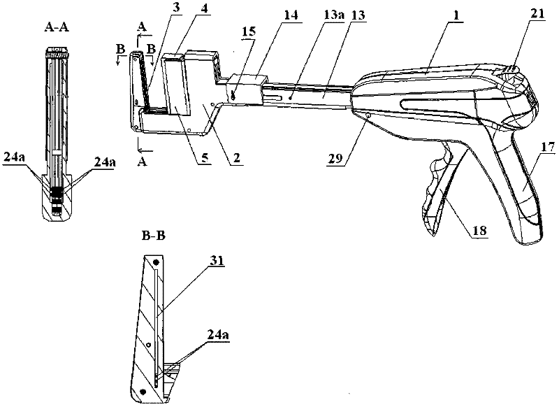
[0044] The cutter and stapler of the present invention comprises a jaw assembly, a connecting assembly connected with the jaw assembly, a jaw driving assembly, a handle assembly, a housing 1 and a cutting device. For the sake of convenience, in the following description, the end away from the operator (that is, the end close to the nail abutment seat) is called the front end, and the end close to the operator (that is, the end close to the fixed handle) is called the rear end.
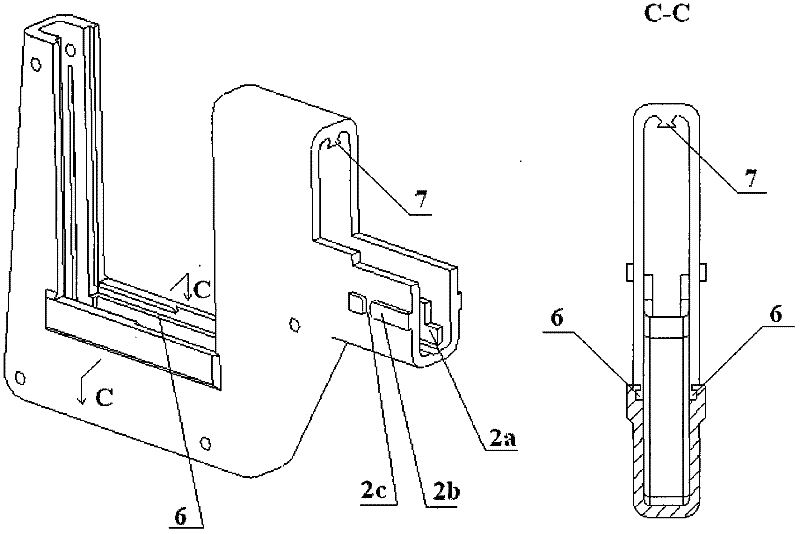
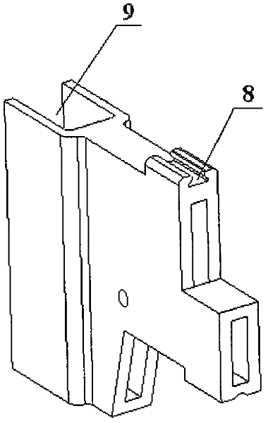
[0045] Such as Figure 1-3 As shown, the jaw assembly includes a nail anvil bracket 2, a nail anvil 3 disposed at the front end of the nail anvil bracket 2, a staple cartridge 4, and a ...
PUM
 Abstract
Description
Claims
Application Information