CAN node, and communication method of communication system including CAN node

a communication system and controller area technology, applied in data switching networks, multiplex communication, digital transmission, etc., can solve the problems of increasing the number of wires, the need for sensor redundancy, and the increment of the transmit error counter and the receive error counter, so as to reduce undelivered messages and avoid excessive traffic.

Active Publication Date: 2013-08-13
RENESAS ELECTRONICS CORP
View PDF6 Cites 27 Cited by
  • Summary
  • Abstract
  • Description
  • Claims
  • Application Information

AI Technical Summary

Benefits of technology

[0020]In this case, a check as to whether the receiving node has received the message successfully is made by software in an upper layer. The checking process includes a query to the receiving node, a receipt notification, and the like. Thus, when retransmission is necessary there is a long latency until the retransmission is actually carried out. Besides, recently, processing performed in vehicles has become more complex and traffic on in-vehicle LANs has been growing steadily. Consequently, there is demand to avoid traffic increases caused by processing of queries intended to check whether reception has been successful, receipt notifications, and the like and reduce loads on bus bands.
[0026]The technique according to the present invention can avoid excessive traffic increases in a CAN system while reducing undelivered messages.

Problems solved by technology

With increases in the number of vehicle-mounted systems, there arise problems such as increases in the number of wires and the need for sensor redundancy.
Generally, however, the transmit error counter is incremented when a transmit error is detected, and is decremented when transmission is successful.
Similarly, the receive error counter is incremented when a receive error is detected, and is decremented when reception is successful.
On the other hand, the Error Passive state is prone to errors.
For example, as shown in FIG. 12, node A and node B are in Error Active state, but node C has fallen into Error Passive state, causing frequent local errors due to a local failure.
Thus, when retransmission is necessary there is a long latency until the retransmission is actually carried out.
Besides, recently, processing performed in vehicles has become more complex and traffic on in-vehicle LANs has been growing steadily.

Method used


Image

  • CAN node, and communication method of communication system including CAN node
  • CAN node, and communication method of communication system including CAN node
  • CAN node, and communication method of communication system including CAN node

Examples


first exemplary embodiment

[0041]A first exemplary embodiment of the present invention will be described below with reference to the accompanying drawings. Incidentally, various components described below and shown in the drawings as being functional blocks which perform various processes can be implemented in terms of hardware by a processor, a memory, or other circuits or implemented in terms of software by a program or the like recorded or loaded in memory. Thus, as will be understood by those skilled in the art, the functional blocks can be implemented by hardware alone, software alone, or combination thereof, and are not restricted to any one of them. Also, for ease of understanding, only those components which are needed in order to describe the technique according to the present invention are illustrated in the drawings. Besides, in the description, the terms “message” and “frame” are used interchangeably.

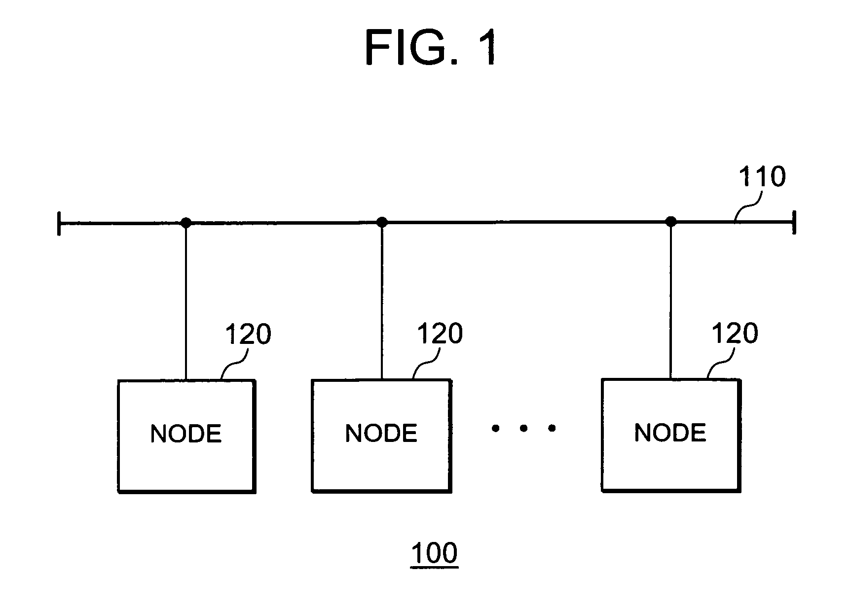
[0042]FIG. 1 shows a CAN system 100 according to the first exemplary embodiment of the present inv...


PUM


Abstract

A Controller Area Network (CAN) node includes a conversion and retransmission unit which retransmits a transmit message if the transmit message carries a retransmission ID out of ID codes, by changing the ID code of the transmit message to a retransmission-specific ID corresponding to the retransmission ID, where the ID codes indicate priorities of transmit messages, the retransmission ID indicates that the transmit message is to be retransmitted, and the retransmission-specific ID is an ID code specifically for use in retransmission, and a conversion and reception unit which checks whether an original message corresponding to a retransmit message has been received successfully, the retransmit message being a receive message carrying the retransmission-specific ID, and discards the retransmit message if the original message corresponding to the retransmit message has been received successfully, but converts the ID code of the retransmit message into a retransmission ID corresponding to the retransmission-specific ID if the original message corresponding to the retransmit message has not been received successfully.

Description

INCORPORATION BY REFERENCE[0001]This application is based upon and claims the benefit of priority from Japanese Patent Application No. 2008-319986 which was filed on Dec. 16, 2008, the disclosure of which is incorporated herein in its entirety by reference.BACKGROUND OF THE INVENTION[0002]1. Field of the Invention[0003]The present invention relates to a communications technique for a Controller Area Network (CAN) system.[0004]2. Description of Related Art[0005]Recent vehicles are equipped with a wide variety of electronic control systems which are used to control an engine's ignition timing, used for a gear box, used for an Anti-Block System (ABS), and so on. With increases in the number of vehicle-mounted systems, there arise problems such as increases in the number of wires and the need for sensor redundancy. Besides, if higher performance is pursued, it becomes necessary to control the systems integrally or in a cooperative manner.[0006]To control systems integrally or in a coope...

Claims


Application Information

Patent Timeline
Patent Type & Authority Patents(United States)
IPC IPC(8): H04L12/28
CPCH04L12/40006H04L12/40013H04L1/1887H04L12/40169H04L12/40163H04L2012/40215
Inventor YAKASHIRO, MASATAKA
Owner RENESAS ELECTRONICS CORP
Why Eureka
Try Eureka