Image processing apparatus and image processing method

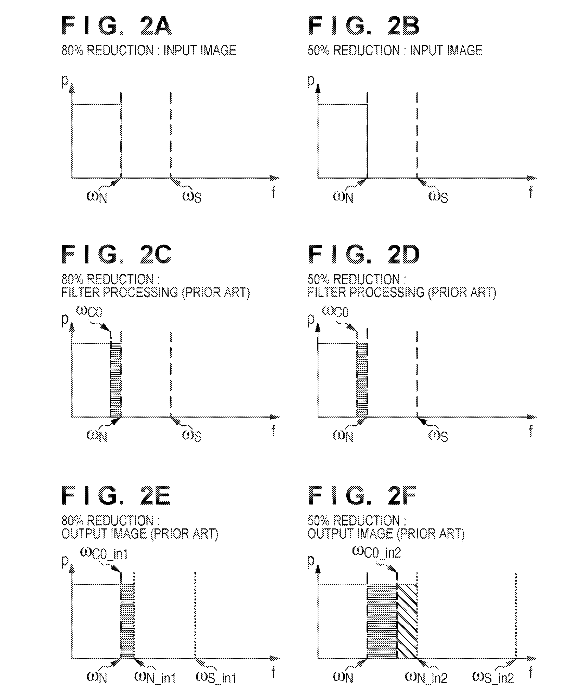
a technology of image processing and image quality, applied in the field of image processing equipment and image processing methods, can solve problems such as moire in images, deterioration in image quality, etc., and achieve the effect of good image quality

Inactive Publication Date: 2013-08-20
CANON KK
View PDF6 Cites 5 Cited by
  • Summary
  • Abstract
  • Description
  • Claims
  • Application Information

AI Technical Summary

Problems solved by technology

With a reduction in image, high-frequency components of the spatial frequency components of the image become aliasing noise, resulting in image deterioration such as moire.
For this reason, the conventional technique has a problem that an image excessively blurs and moire remains, resulting in a deterioration in image quality.

Method used


Image

  • Image processing apparatus and image processing method
  • Image processing apparatus and image processing method
  • Image processing apparatus and image processing method

Examples


first embodiment

[0026][First Embodiment]

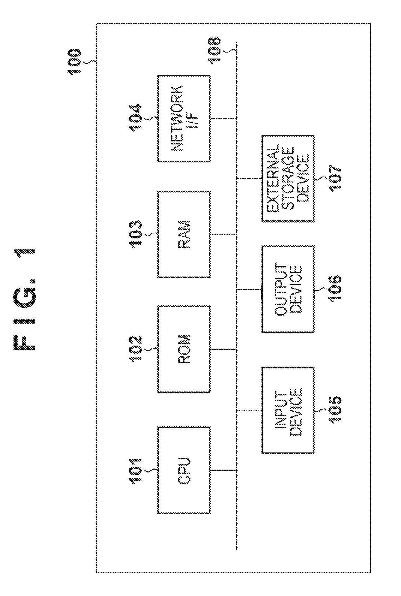
[0027]An example of the hardware arrangement of a computer 100 functioning as an image processing apparatus will be described first with reference to the block diagram of FIG. 1. Note that FIG. 1 shows only components which are mainly used for the following description. It is possible to add other components or omit some of the components in some cases.

[0028]A CPU 101 controls the overall operation of the computer 100 by using computer programs and data which are stored in a ROM 102 and a RAM 103, and executes each process to be described as a process to be executed by the computer 100.

[0029]The ROM 102 stores set data and a boot program for the computer 100. The RAM 103 has an area for temporarily storing computer programs and data acquired via an input device 105 and a network I / F 104 and computer programs and data loaded from an external storage device 107. The RAM 103 further has a work area to be used when the CPU 101 executes various kinds of processes....

second embodiment

[0122][Second Embodiment]

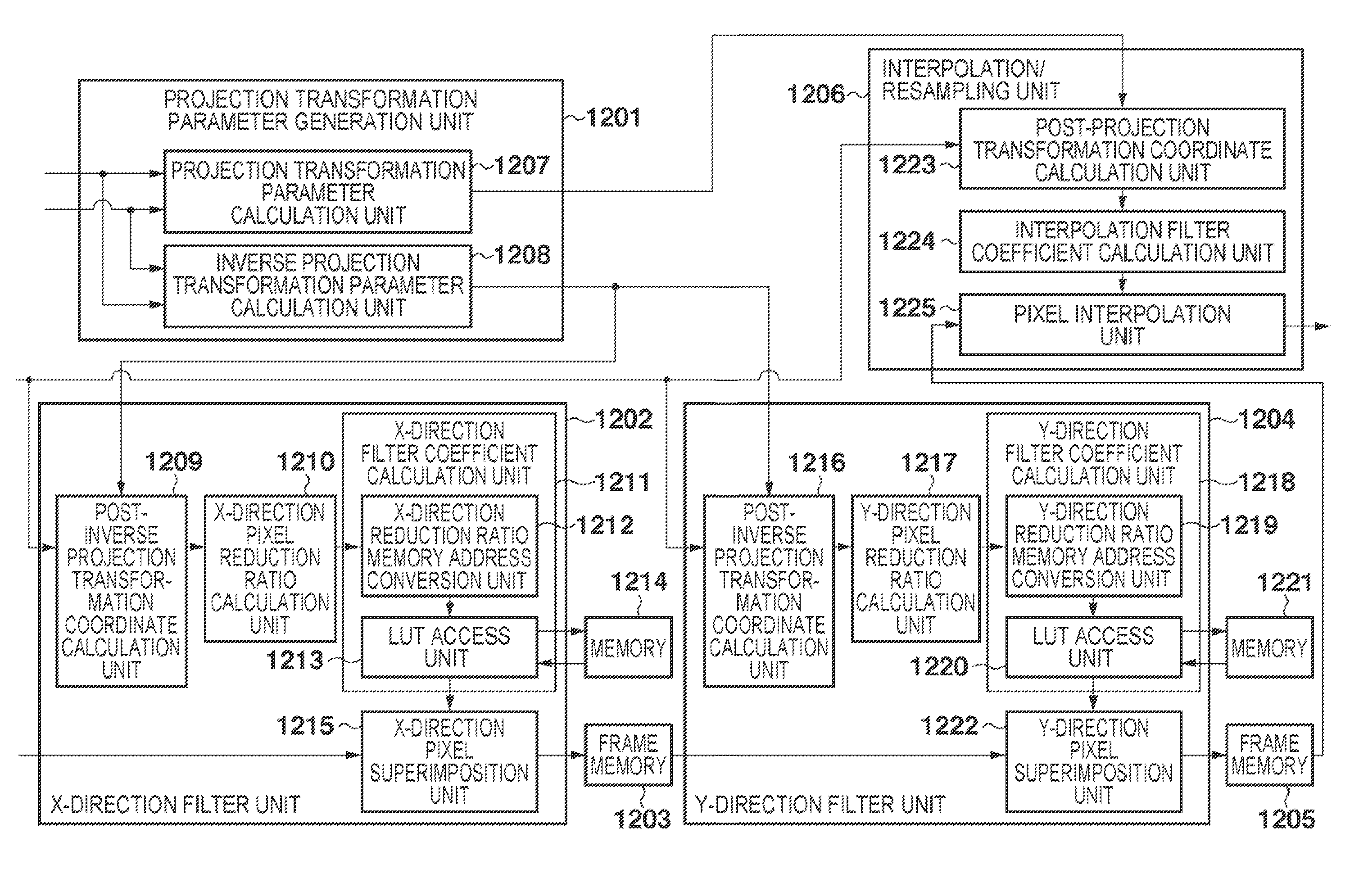
[0123]This embodiment will exemplify a projector apparatus which performs processing similar to that performed by the computer 100 described in the first embodiment. An example of the hardware arrangement of a projector apparatus 1101 according to this embodiment will be described with reference to the block diagram of FIG. 11.

[0124]A reception unit 1105 receives broadcast waves via antennas 1102, 1103, and 1104, and decodes them into audio and video signals. An I / F unit (not shown) interfaces various kinds of input / output control signals for channel selection, volume control, and image quality correction.

[0125]An audio processing unit 1113 in a signal processing unit 1112 properly processes an audio signal from the reception unit 1105, and outputs the resultant signal to an audio driving unit 1116. A video processing unit 1115 in the signal processing unit 1112 performs various kinds of processes (to be described later) for a video signal from the reception...


PUM


Abstract

A CPU generates an image by performing inverse projection transformation for an input image by using an inverse matrix of a matrix which enlarges a size of the input image. When a position A on the input image is transformed into a position B on the generated image by the inverse projection transformation, the CPU obtains a ratio of a distance between pixels around the position B to a distance between pixels around the position A. The CPU calculates filter coefficients for a low-pass filter using a product of a Nyquist frequency of the input image and the ratio as a cutoff frequency. The CPU obtains a sum of results obtained by multiplying pixel values of pixels in a pixel array including the position A in the input image by the filter coefficients, as a pixel value at the position A in an image having undergone filter processing.

Description

BACKGROUND OF THE INVENTION[0001]1. Field of the Invention[0002]The present invention relates to an image processing technique and, more particularly, to a keystone correction processing technique for correcting keystone distortion in a front projector or the like.[0003]2. Description of the Related Art[0004]As a technique of electronically correcting trapezoidal distortion of an image which occurs when a liquid crystal projector projects the image on a screen, an electronic trapezoidal distortion correction processing technique has been conventionally known (Japanese Patent Laid-Open No. 2009-44488).[0005]The electronic trapezoidal distortion correction processing technique deforms the shape of an image so as to cancel out trapezoidal distortion to project the resultant image as an image having the same shape as that of the original image. Performing interpolation / resampling processing will generate an image corresponding to the deformed shape.[0006]The electronic trapezoidal disto...

Claims


Application Information

Patent Timeline
Patent Type & Authority Patents(United States)
IPC IPC(8): G06T5/00
CPCG06T3/0006
Inventor SATO, YOSUKE
Owner CANON KK
Why Eureka
Try Eureka