
Electronic timepiece and reception control method for an electronic timepiece

a technology of electronic timepiece and electronic clock, which is applied in the direction of setting time indication, instruments, and horology, can solve the problems of heavy processor load, long search time, and burdensome processor load, and achieve the effect of low processor load and easy acquisition of leap second reception time information

Active Publication Date: 2013-08-20
SEIKO EPSON CORP
View PDF9 Cites 4 Cited by
  • Summary
  • Abstract
  • Description
  • Claims
  • Application Information

AI Technical Summary

Benefits of technology

[0008]An electronic timepiece and reception control method for an electronic timepiece according to the invention can easily acquire leap second reception time information with a low processor load.

Problems solved by technology

This applies a burdensome load on the processor if a low power processor is used.
JP-A-2008-145287 also describes storing calculated leap second reception times in memory, but searching for the reception time takes too long if all reception times are stored because of the large amount of data.
This results in a heavy load on the processor if a low power processor is used.

Method used


Image

  • Electronic timepiece and reception control method for an electronic timepiece
  • Electronic timepiece and reception control method for an electronic timepiece
  • Electronic timepiece and reception control method for an electronic timepiece

Examples


embodiment 2

[0125]FIG. 10 is a flow chart of the reception control process according to a second embodiment of the invention. Steps that are the same as in the process used in the first embodiment shown in FIG. 9 are identified by like reference numerals and further description thereof is omitted.

[0126]The leap second reception time tables in this embodiment of the invention express the start-reception time in terms of UTC by using a UTC offset of 15 seconds and subtracting the UTC offset from GPS time. The operation of step S0 in FIG. 9 is not performed in this second embodiment, and a reference time is therefore not generated. As a result, the internal time is used for comparison in S1 and S2. The table correlating the five minute-second combinations of the leap second reception time shown in FIG. 8A to the hours from 0 to 23, and the weekdays from Sunday to Saturday, also does not change in this embodiment.

[0127]However, the table correlating the table number to the minute-second combination...


PUM


Abstract

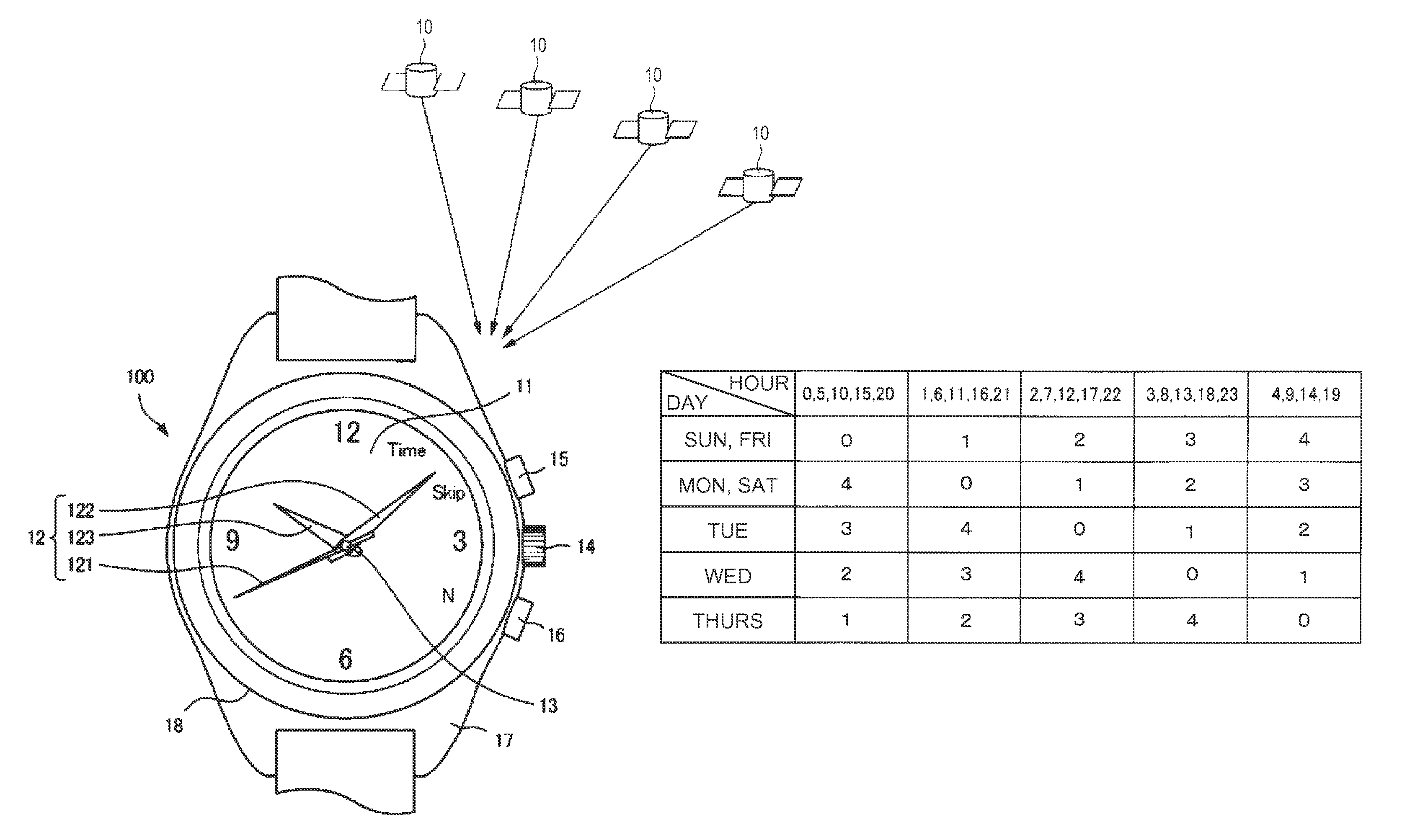
An electronic timepiece can easily acquire a leap second information reception time with minimal processor load. A first table groups leap second information reception times expressed by hour, minute, second, and day values into plural minute-second patterns of minute-second combinations that are common to plural hours, and relates numbers identifying these minute-second patterns to the day and hour values. The minute-second combinations are grouped by number in a second table. The number corresponding to the day and hour of the internal time is found from the first table (S1). A minute-second combination that is later than the internal time is found from the minute-second combinations corresponding to the acquired number (S2). And leap second reception time is calculated. If the resulting leap second reception time matches the internal time is determined (S9). If the times match, the leap second information is received (S10, S11).

Description

CROSS-REFERENCE TO RELATED APPLICATION[0001]The entire disclosure of Japanese Patent Application No. 2011-026510, filed Feb. 9, 2011 is expressly incorporated by reference herein.BACKGROUND[0002]1. Technical Field[0003]The present invention relates to an electronic timepiece that receives satellite signals transmitted from positioning information satellites such as GPS satellites to obtain current date and time information, and to a reception control method for an electronic timepiece.[0004]2. Related Art[0005]Japanese Unexamined Patent Appl. Pub. JP-A-2008-145287 teaches a leap second correction method for acquiring subframe and page identification information from navigation data, and calculating the time when leap second correction data will be received from the subframe and page identification information. This leap second correction method stores the calculated leap second reception time in a storage unit.[0006]The method taught in JP-A-2008-145287 digitizes the page number and...

Claims


Application Information

Patent Timeline
Patent Type & Authority Patents(United States)
IPC IPC(8): G04C11/00G04G5/00G04R20/06
CPCG04R20/06
Inventor AKIYAMA, TOSHIKAZUJAEKWAN, OH
Owner SEIKO EPSON CORP
Learn More