
Device and method for serial data transmission between a position-measuring device and a control unit

a technology of position-measuring devices and control units, which is applied in the direction of transmission, programme control, instruments, etc., to achieve the effect of reducing the number of lines needed for data transmission

Active Publication Date: 2013-08-27
DR JOHANNES HEIDENHAIN GMBH
View PDF13 Cites 2 Cited by
  • Summary
  • Abstract
  • Description
  • Claims
  • Application Information

AI Technical Summary

Benefits of technology

The present invention is about a device that can transmit data quickly and using fewer wires. This device allows for flexible data transmission at different speeds.

Problems solved by technology

An important cost factor in the connection of position-measuring devices to sequential electronics, e.g., a machine-tool control, is based on the number of connecting lines needed, since they substantially determine the price of the high-quality data cable used.

Method used


Image

  • Device and method for serial data transmission between a position-measuring device and a control unit
  • Device and method for serial data transmission between a position-measuring device and a control unit
  • Device and method for serial data transmission between a position-measuring device and a control unit

Examples


Embodiment Construction

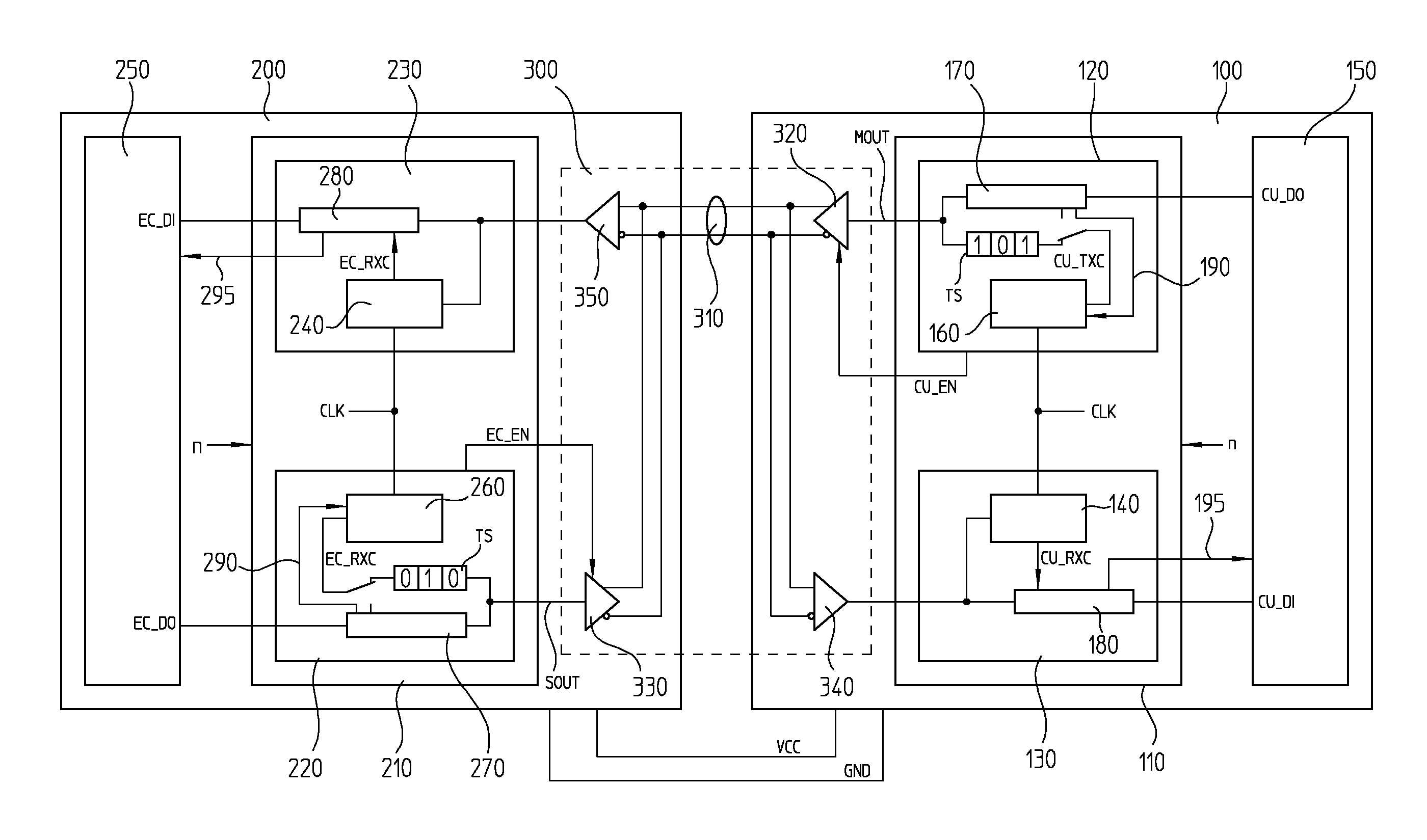
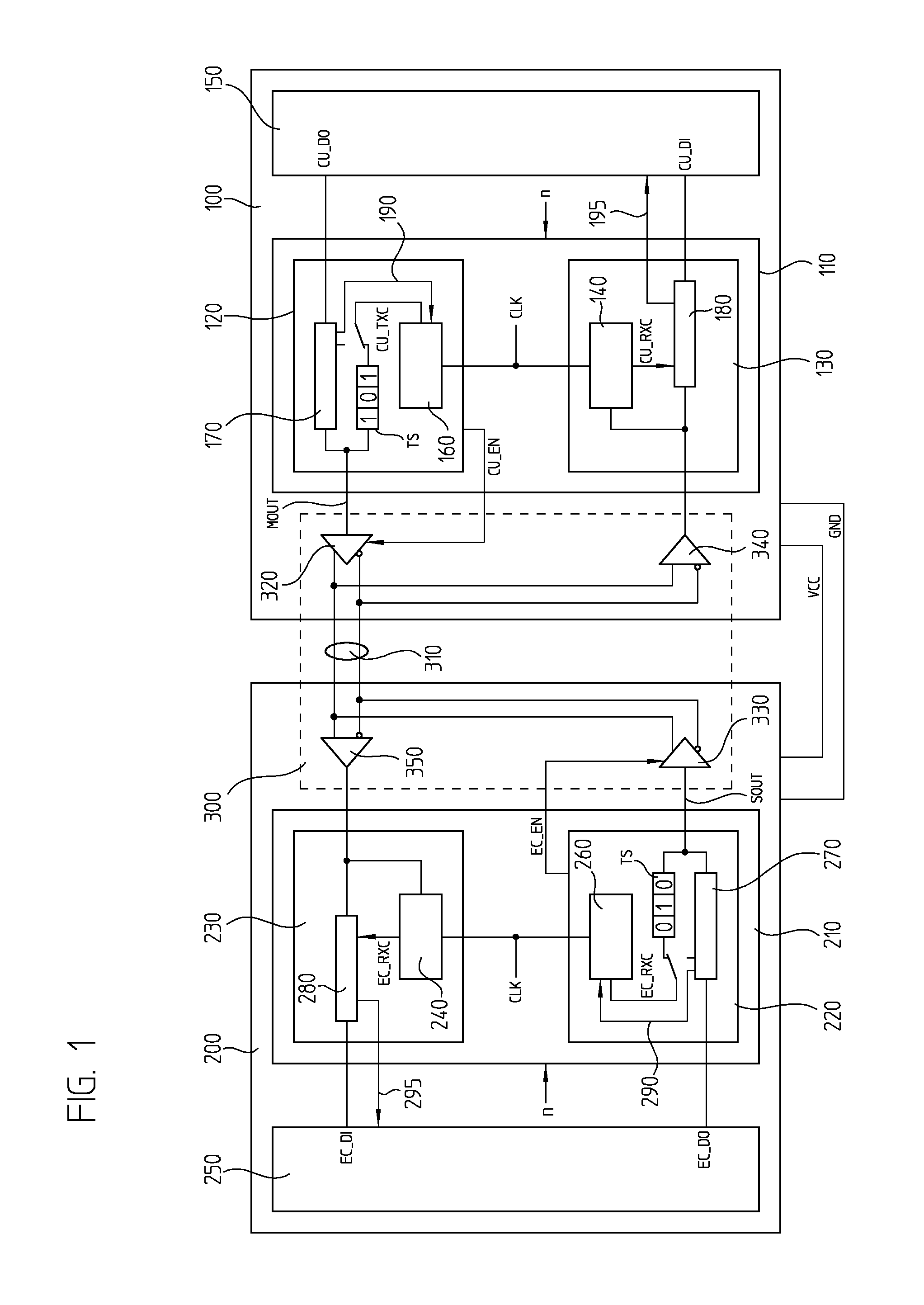
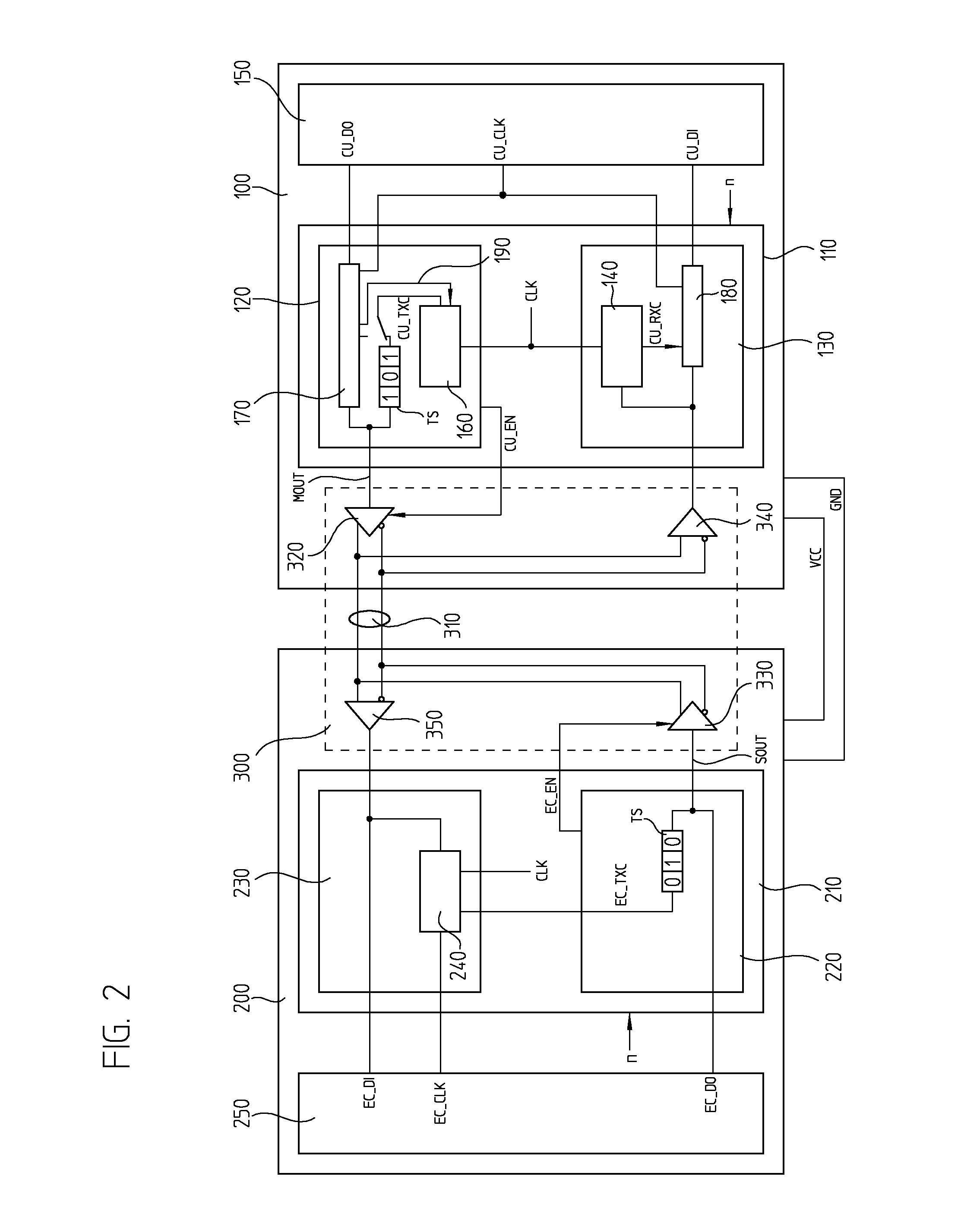
[0021]FIG. 1 shows a block diagram of a device for serial data transmission between a control unit 100 and a position-measuring device 200. For the exchange of data, an interface unit 110 on the control side is disposed in control unit 100, and an interface unit 210 on the measuring-device side is disposed in position-measuring device 200, which are connected to each other via a serial, bidirectional data channel 300. In order to transmit data from control unit 100 to position-measuring device 200, a control-side transmitter unit 120 is disposed in interface unit 110 on the control side, and a measuring-device-side receiver unit 230 is disposed in interface unit 210 on the measuring-device side. Analogous thereto, data are transmitted in the reverse direction via a transmitter unit 220 on the measuring-device side and a receiver unit 130 on the control side.

[0022]The power supply may be fed to position-measuring device 200 via supply lines VCC, GND by control unit 100.

[0023]A data c...


PUM


Abstract

In a device and a method for serial data transmission between a position-measuring device and a control unit, made up of an interface unit on the control side and an interface unit on the measuring-device side, which are connected to each other for the transmission of serial data packets with the aid of a bidirectional data channel, the interface unit on the control side includes a control-side transmitter unit for transmitting serial data packets via the data channel to a measuring-device-side receiver unit disposed in the interface unit on the measuring-device side. The interface unit on the measuring-device side includes a measuring-device-side transmitter unit for transmitting serial data packets via the data channel to a control-side receiver unit disposed in the interface unit on the control side. Data packets transmitted by the control-side transmitter unit include a clock sequence at the beginning, from whose time characteristic it is possible to derive the frequency of a control-side transmitter clock signal underlying the transmission. The receiver unit on the measuring-device side includes a measuring-device-side clock-recognition unit which evaluates the clock sequence and, in order to read in control-side output data included in the data packet, generates a measuring-device-side receiver clock signal, whose frequency corresponds to a great extent to that of the transmitter clock signal on the control side.

Description

FIELD OF THE INVENTION[0001]The present invention relates to a device for serial data transmission as well as to a method for serial data transmission. Such a device and a method permit a bidirectional data transmission via a single one-channel data line.BACKGROUND INFORMATION[0002]Position-measuring devices which provide an absolute position value are being used increasingly in automation technology. Certain disadvantages of what are termed incremental position-measuring devices are thereby eliminated such as, for example, the necessity of carrying out a reference run after switching on in order to find a reference position which is used as reference point for the further position measuring by counting graduation marks.[0003]Primarily serial data interfaces are used for transmitting the absolute position values, since they make do with only a few data-transmission lines, and nevertheless, have high data-transmission rates. Particularly advantageous here are what are called synchron...

Claims


Application Information

Patent Timeline
Patent Type & Authority Patents(United States)
IPC IPC(8): H04J3/06H04L12/28
CPCH04L5/14H04L7/044H04L25/4904G05B2219/33187
Inventor BEAURY, BERNHARDHELLMICH, HEIK H.STRASSER, ERICH
Owner DR JOHANNES HEIDENHAIN GMBH
Learn More