Picture coding method and picture coding apparatus

a picture coding and picture technology, applied in the field of picture coding methods and picture coding apparatuses, can solve the problems of not being able to send video for a television and a camera, not being able to handle these massive amounts of multimedia information in digital form, and affecting the quality of the picture, so as to reduce the computational complexity, improve the compression rate, and reduce the frequency of stream transmission loss

Active Publication Date: 2013-08-27
PANASONIC CORP
View PDF17 Cites 6 Cited by
  • Summary
  • Abstract
  • Description
  • Claims
  • Application Information

AI Technical Summary

Benefits of technology

[0097]According to an implementation of the present invention, the picture coding method and the picture coding apparatus for reducing the computational complexity and improving the compression rate can be implemented, while reducing the frequency of the stream transmission loss without interfering with the pipelining and paralleling.
[0098]More specifically, the picture coding method and the picture coding apparatus according to an implementation of the present invention allow for dividing pictures into slices so that the size of an I-slice (the number of blocks) can be smaller than that of P slice (the number of blocks). Thereby, there are advantages that (1) the number of slices in a picture can be reduced and increase in the computational complexity and decrease in a compression rate can be prevented, and (2) the number of bits of the I-slices can be smaller and the I-slices that are important for preventing the continuation of deterioration in the picture quality can be less subject to the loss in a part of a stream.

Problems solved by technology

It is therefore not practical to handle these massive amounts of the multimedia information in digital form.
For example, video telephony service is available over Integrated Services Digital Network (ISDN) lines with a transmission speed of 64 Kbit / s to 1.5 Mbit / s, but video for a television and a camera cannot be sent as it is over the ISDN lines.
When coded picture data, that is, a stream is transmitted through a network, a part of the stream may be lost due to network congestions and / or others.
When the part of the stream is lost, the receiver cannot accurately decode a picture corresponding to the lost part of the stream.
In other words, picture quality of the subsequent pictures is continuously deteriorated.
Even when a decoder receives the stream of the slices without any loss in the transmission path and decodes the stream per slice, there is no guarantee that pixels that have been processed to be decoded cannot be accurately decoded.
Thus, when a picture with deteriorated picture quality due to a loss in a part of the stream in previous time is referred to, the pixels of the picture cannot be accurately decoded.
Thus, there is a problem that, when a part of stream is lost and a picture subsequent to the lost part of the stream is inter coded, the picture cannot be accurately decoded, and recursively, pictures subsequent to the picture cannot be accurately decoded.

Method used


Image

  • Picture coding method and picture coding apparatus
  • Picture coding method and picture coding apparatus
  • Picture coding method and picture coding apparatus

Examples


embodiment 1

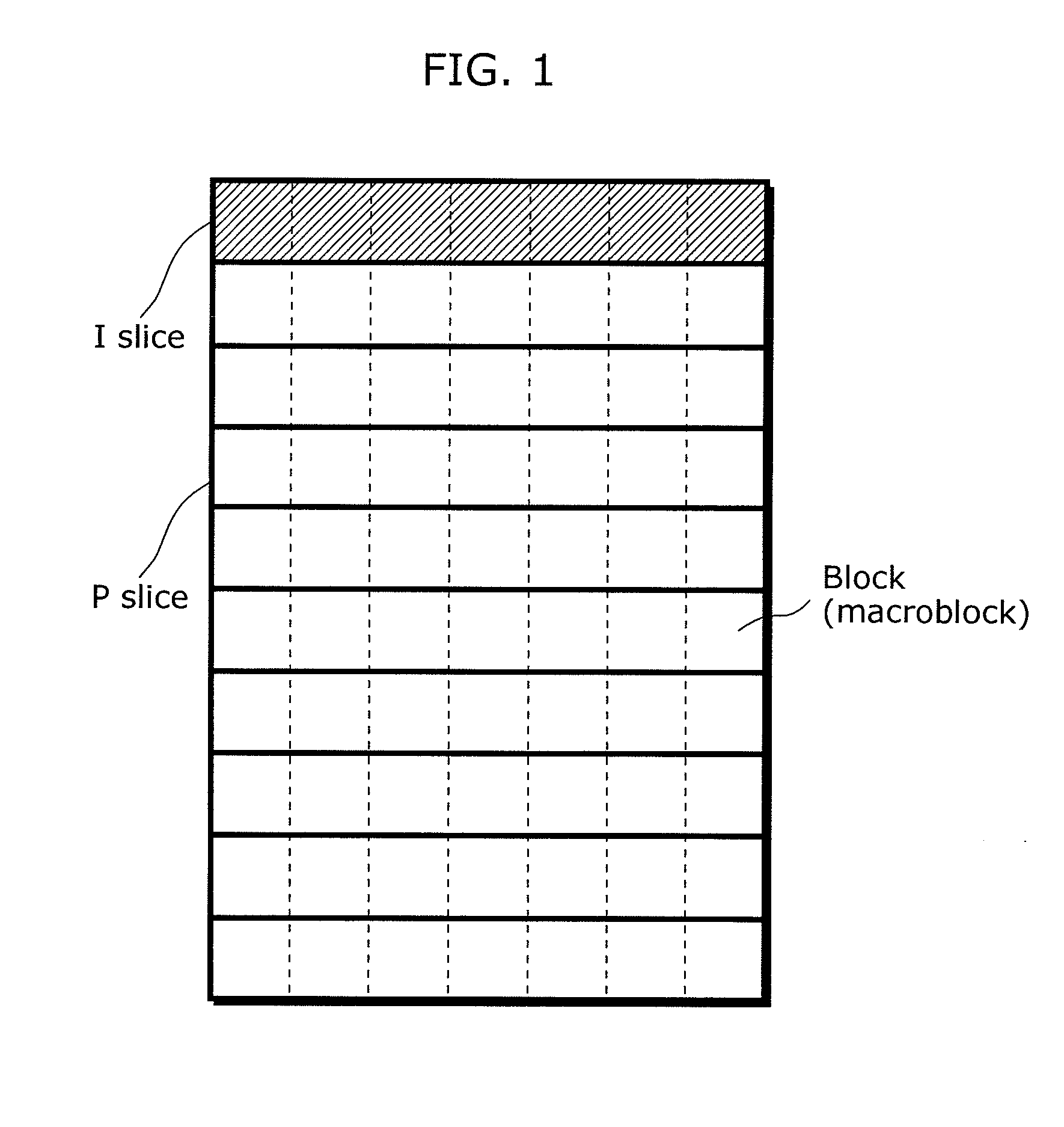
[0219]FIG. 11 is an explanatory drawing showing a relationship between slices and blocks using a slice division method according to Embodiment 1 in the present invention. The picture (1 frame) in FIG. 11 is composed of blocks. Among the blocks composing the picture, an area of diagonally shaded blocks indicates a slice, that is, an I-slice. The blocks enclosed by thick lines compose another slices, that is, P slices. The example herein indicates that the picture is composed of I-slices and P slices. The difference with the slice division method in accordance with MPEG-2 in FIG. 1 is that blocks included in an I-slice is smaller in number than that of a P slice (slice size is smaller) in the slice division method in the present invention.

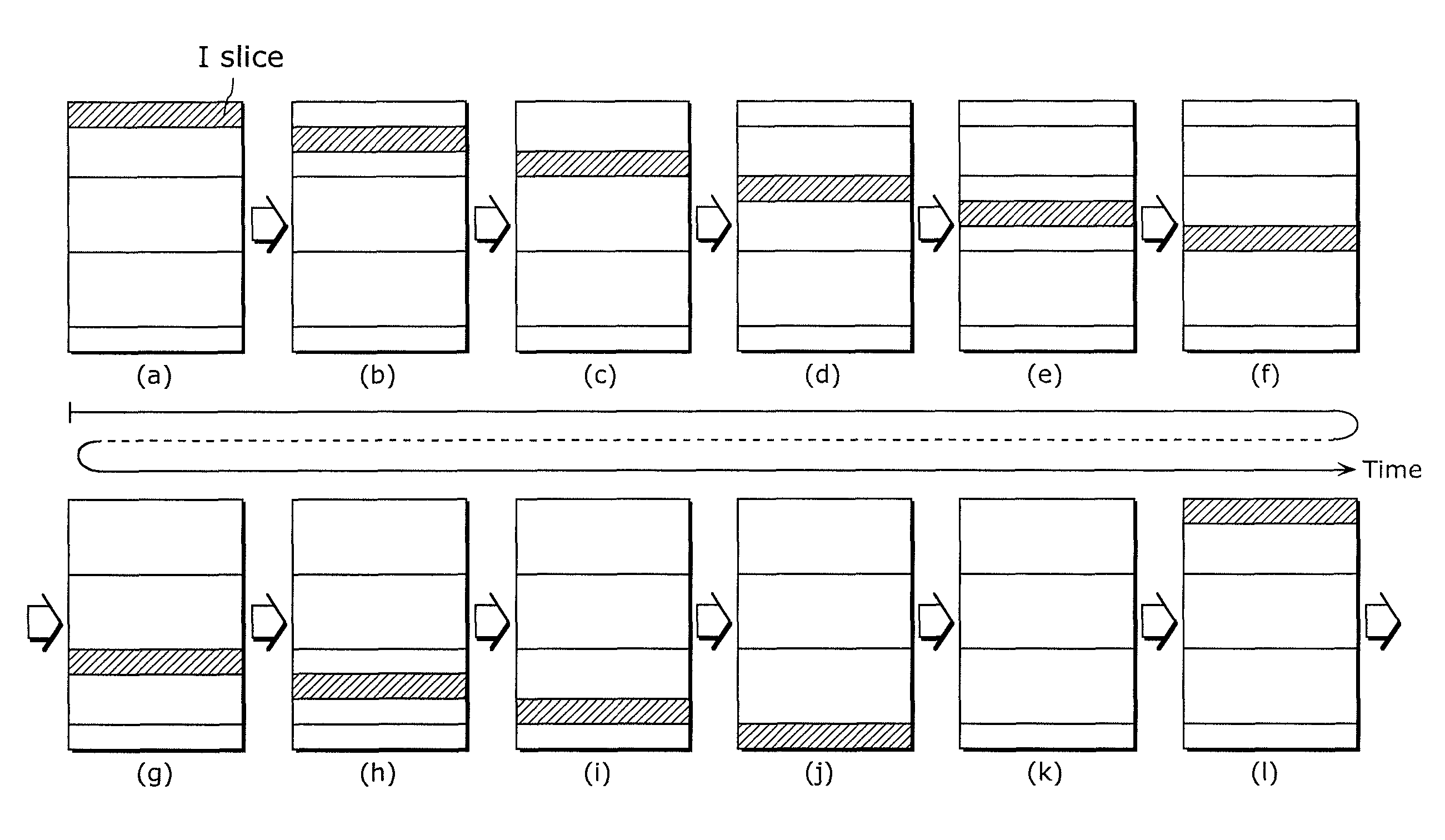
[0220]FIG. 12 illustrates an example of divided slices in pictures that are temporally consecutive according to Embodiment 1 in the present invention. The diagonally shaded slices indicate I-slices, and the rest of the slices indicate P slices.

[0221]...

embodiment 2

[0248]Next, Embodiment 2 will be hereinafter described. The description of the same configuration and operations as those of Embodiment 1 will be omitted.

[0249]FIG. 15 illustrates an example of divided slices in pictures that are temporally consecutive according to Embodiment 2 in the present invention. The diagonally shaded slices are I-slices, and other slices are P slices. The difference with the slice division method in FIG. 12 according to Embodiment 1 is that in the slice division method in FIG. 15 according to Embodiment 2, the size of the P slices immediately subsequent to the I-slices is fixed (N blocks), and the boundary position (slice division position) between P slices that are below the I-slice are moved down by the number of rows corresponding to I-slices.

[0250]Thus, the number of slices included in the pictures according to Embodiment 2 is smaller than that of Embodiment 1. For example, FIG. 15 is compared with FIG. 12. Comparison between (a) in FIG. 12 and (a) in FI...

embodiment 3

[0253]Next, Embodiment 3 will be hereinafter described. The same configuration and operations as those of Embodiments 1 and 2 will be omitted.

[0254]FIG. 17 illustrates an example of divided slices in pictures that are temporally consecutive according to Embodiment 3 of the present invention. The diagonally shaded slices are I-slices, and other slices are P slices.

[0255]Embodiment 1 shows the example that all of the pictures include I-slices except for the pictures between the pictures each having the I-slice in the lowest row and the pictures each having the I-slice in the highest row. In Embodiment 3, assumed is a case where the quality of network is higher and the I-slices may be less frequently inserted. In such a case, as shown in FIG. 17, a picture having no I-slice is regularly inserted.

[0256]When a stream is reproduced, in general, at least one I picture is desirably said to be inserted in the stream that lasts 2 seconds. For example, when 30 frames are needed per second for ...


PUM


Abstract

A picture coding apparatus that reduces a computational complexity, improves a compression rate, and reduces frequency of stream transmission loss without interfering with pipelining and paralleling includes: a dividing unit that divides a picture into an I-slice and a P slice, each of the I-slice and P slice including blocks; and a coding unit that codes each slice per block so as to code temporally consecutive pictures, wherein the dividing unit changes a position of the I-slice in each of the temporally consecutive pictures so that positions of I-slices circulate in a to-be-determined number of pictures among the temporally consecutive pictures, and divides each of the temporally consecutive pictures so that a sum of the number of blocks included in the I-slice and the number of blocks included in one or more P slices between the I-slice and an I-slice subsequent to the I-slice becomes a predetermined value.

Description

TECHNICAL FIELD[0001]The present invention relates to a picture coding method and a picture coding apparatus, and particularly to a picture coding method and a picture coding apparatus for dividing a picture signal into slices each including blocks, and coding, per block, each of the slices, in accordance with the Moving Picture Experts Group (MPEG)-4 standard or the ITU-T H.264 standard.BACKGROUND ART[0002]Recently, with the advent of the age of multimedia which handles audio, pictures and other pixel values in an integrated manner, conventional information media, such as newspapers, journals, TVs, radios, and telephones, through which information is carried to people, have come under the scope of multimedia. Generally, multimedia refers to a representation in which not only text but also graphics, audio, particularly pictures, and / or others are simultaneously associated with one another. The information for the above conventional information media must first be digitized before it...

Claims


Application Information

Patent Timeline
Patent Type & Authority Patents(United States)
IPC IPC(8): H04N7/12H04N19/50H04N19/107H04N19/134H04N19/174H04N19/189H04N19/196H04N19/503H04N19/51H04N19/65
CPCH04N19/61H04N19/174H04N19/107
Inventor KADONO, SHINYA
Owner PANASONIC CORP
Why Eureka
Try Eureka