Boundary microphone

a microphone and boundary technology, applied in the field of boundary microphones, can solve the problems of insufficient electrostatic shielding against considerably strong electromagnetic waves radiated from mobile phones, remain some problems to be solved, and difficult to uniformly maintain, so as to achieve the effect of facilitating uniform wiring shapes

Inactive Publication Date: 2013-08-27
AUDIO-TECHNICA
View PDF4 Cites 6 Cited by
  • Summary
  • Abstract
  • Description
  • Claims
  • Application Information

AI Technical Summary

Benefits of technology

[0018]According to the invention, as a metallic holder for mounting the microphone unit in an opening formed on the circuit board, there is provided a holder including a cylindrical section into which a rear end side of the microphone unit is fitted, and a D-cut section in which a part of a circumferential surface and a base surface of a cylinder with a base integral with the cylindrical section is cut away in parallel to a board surface of the circuit board, and a lead wire from the microphone unit to the circuit board is routed within the D-cut section. This provides sufficient electrostatic shielding on the portion of a lead wire, and noises caused by external electromagnetic waves can efficiently be reduced.
[0021]In addition, since an uncoated solder plated wire is used for the lead wire, it is easier to provide uniform wiring shapes. Therefore, even if a noise is generated, it is easy to address the noise in the design because the frequency that undergoes interference can be invariable.

Problems solved by technology

The base plate 10 and the cover 20 are in contact with each other and in a conductive state in terms of DC; however, they suffer from insufficient electrostatic shielding against considerably strong electromagnetic waves radiated from a mobile phone.
Therefore, when the mobile phone is used near the boundary microphone, a high frequency current caused by the electromagnetic waves may flow in the microphone and may be detected by a semiconductor device such as the FET mounted on the circuit board 30, causing a noise.
Although this reduces noises caused by external electromagnetic waves to some extent, there still remain some problems to be solved.
In addition, since the lead wires 42, 42 are of coated type, which makes it difficult to uniformly maintain the shape of wires, another problem is that frequencies of electromagnetic waves that cause noises and the levels of the noises are non-uniform.

Method used


Image

  • Boundary microphone
  • Boundary microphone
  • Boundary microphone

Examples


Embodiment Construction

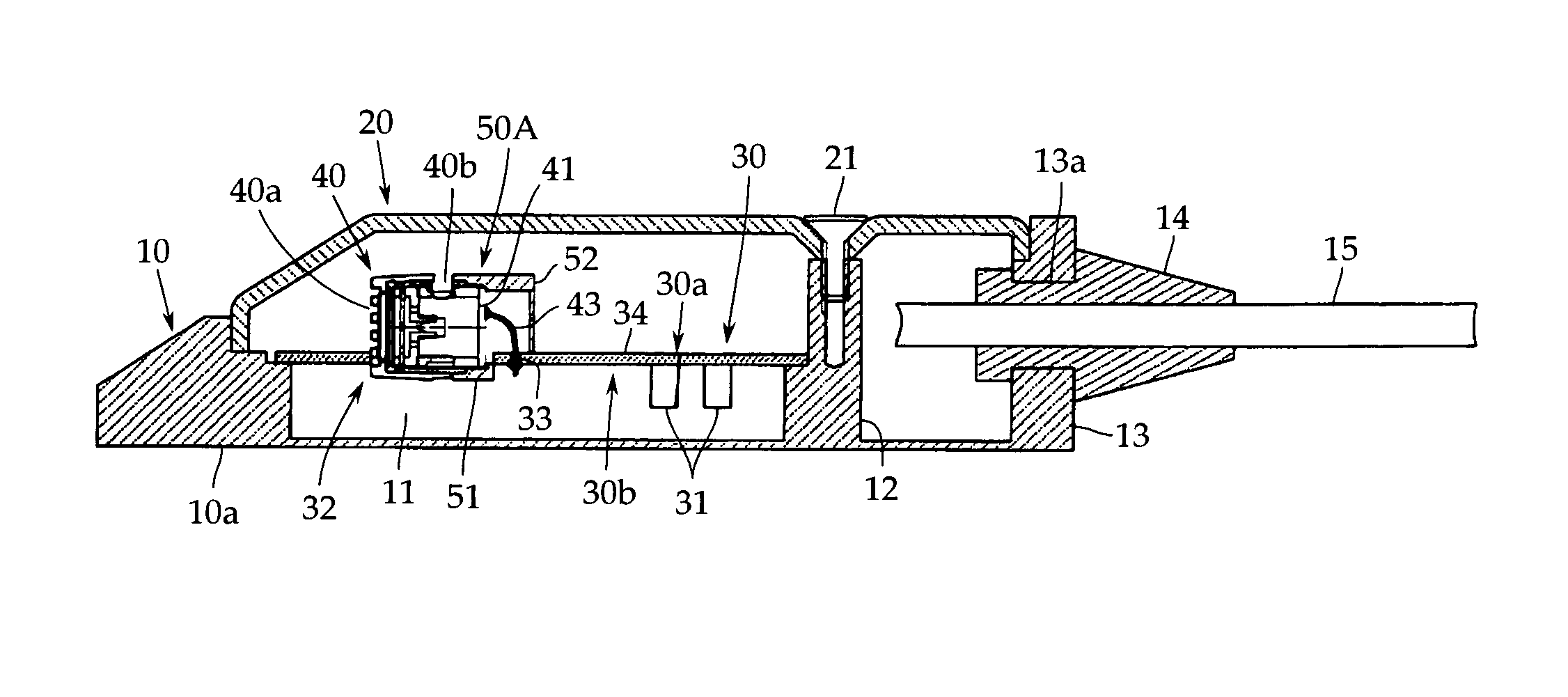
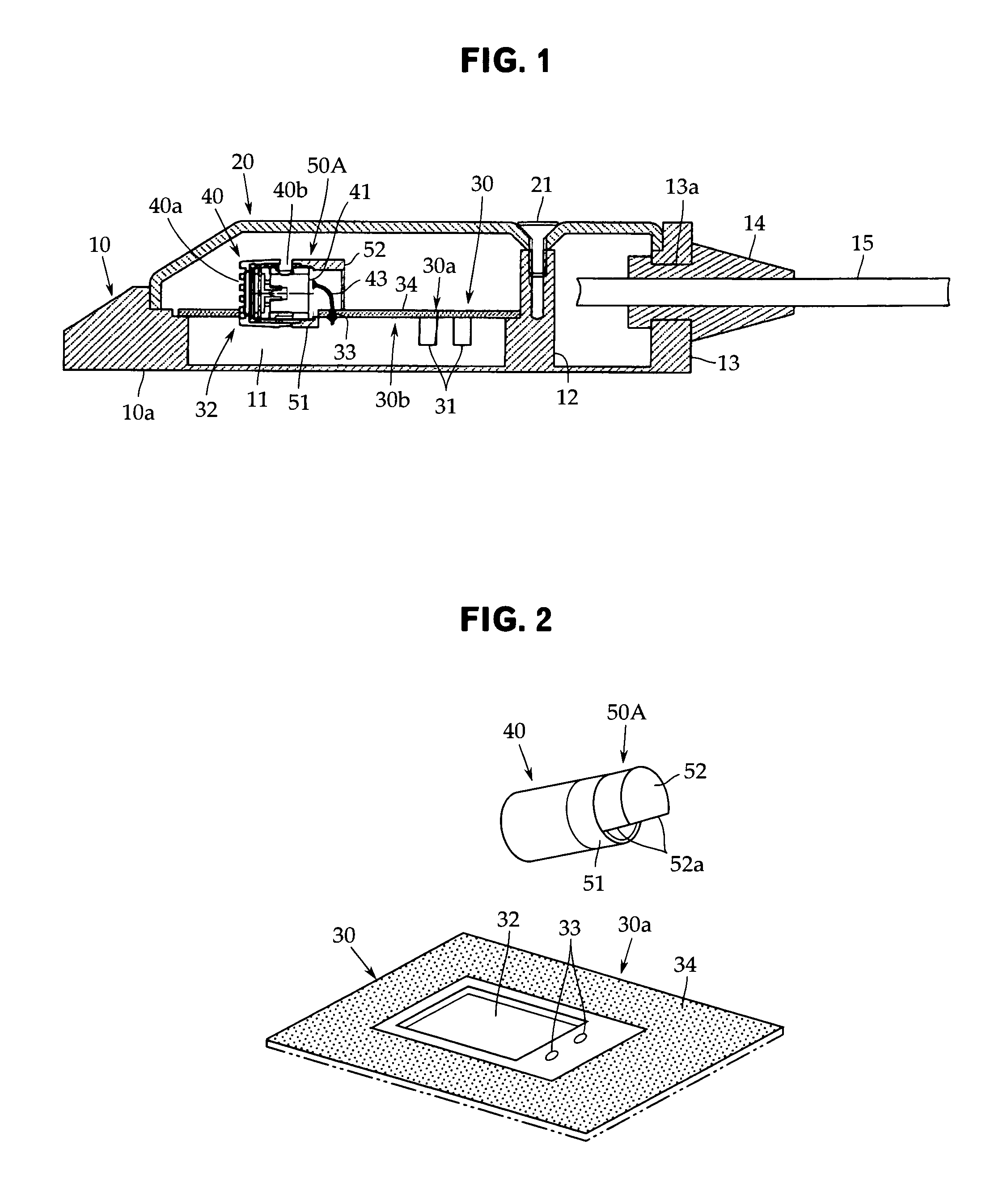
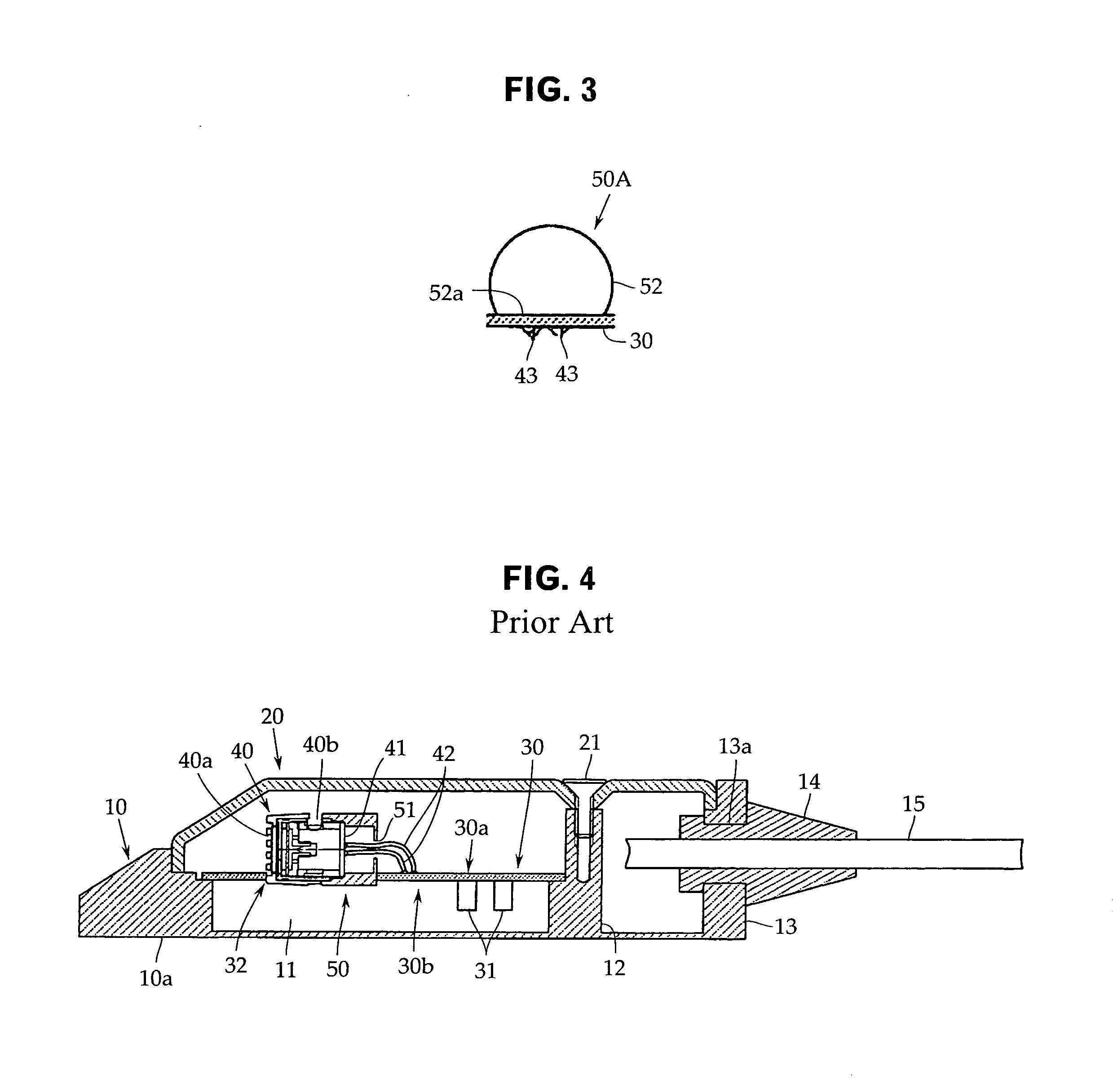
[0026]An embodiment of the invention will now be described with reference to FIGS. 1 to 3, although the present invention is not limited to the embodiment. In the description of the embodiment, like reference numerals are used to denote any components that do not require changes from the prior art in FIG. 4 as described above.

[0027]As shown in FIG. 1, a boundary microphone according to the embodiment also includes a base plate 10 and a cover 20 closing the base plate 10, similarly to the prior art as described above.

[0028]The base plate 10, whose base surface 10a is formed flat so that the base plate 10 can be placed stably on a table top or a floor, includes a recess 11 for mounting a circuit board and a column 12 for connecting the cover on the upper surface side, and is provided with a backwall 13 that has a microphone cable drawing hole 13a in the rear. The base plate 10 may as a whole be made of die-cast aluminum, for example.

[0029]A punched plate (perforated metal) or a wire m...


PUM


Abstract

A boundary microphone is provided to effectively reduce noises caused by external electromagnetic waves by providing electrostatic shielding, including on the portion of lead wires from a microphone unit to a circuit board. The boundary microphone has a base plate, a cover, a circuit board, and a microphone unit mounted in the opening with a metallic holder. A shield pattern for electrostatically shielding inside of the recess with the base plate is formed on the circuit board. The holder is configured to include a cylindrical section into which a rear end side of the microphone unit is fitted, and a D-cut section in which a part of a circumferential surface and a base surface of a cylinder with a base integral with the cylindrical section are cut away in parallel to a board surface of the circuit board, and the lead wire is routed within the D-cut section.

Description

CROSS-REFERENCE TO RELATED APPLICATION[0001]The present application is based on, and claims priority from, Japanese Application Serial Number JP2010-238309, filed Oct. 25, 2010, the disclosure of which is hereby incorporated by reference herein in its entirety.TECHNICAL FIELD[0002]The present invention relates to a boundary microphone, and in particular to a technique for reducing a noise caused by external electromagnetic waves.BACKGROUND ART[0003]A boundary microphone is a kind of microphone of a flat, low profile shape for use on a table, floor, or the like, and includes a base plate 10 and a cover 20 closing the base plate 10 as shown in FIG. 4.[0004]The base plate 10, whose base surface 10a is flat, includes a recess 11 for mounting a circuit board and a column 12 for connecting the cover on the upper surface side, and is provided with a backwall 13 that has a microphone cable drawing hole 13a in the rear. In many cases, the base plate 10 as a whole is made of die-cast aluminum...

Claims


Application Information

Patent Timeline
Patent Type & Authority Patents(United States)
IPC IPC(8): H04R11/04
CPCH04R1/086
Inventor AKINO, HIROSHI
Owner AUDIO-TECHNICA
Why Eureka
Try Eureka