Noise correction circuit, imaging apparatus, and noise correction method

Inactive Publication Date: 2009-04-23
SONY CORP
View PDF8 Cites 13 Cited by
  • Summary
  • Abstract
  • Description
  • Claims
  • Application Information

AI Technical Summary

Benefits of technology

[0016]By adding a random number at a level not determined by quantization to the image signal, there will be cases where the least significant bit is raised to one or remains unchanged depending on the value of the random number. Accordingly, the value of the least significant bit is prevented from being uniform in the same column, and when the output image signal is displayed, there is no noise in the

Problems solved by technology

With this method, however, it is difficult to correct vertical lines at a level not determined by quantization of the image signal.
This means that if digital amplification is carried out while sufficient light is not input into the image sensor and the output signal level after analogue to digital conversion is low, such vertical lines at a level not determined by quantization and therefore not corrected will

Method used


Image

  • Noise correction circuit, imaging apparatus, and noise correction method
  • Noise correction circuit, imaging apparatus, and noise correction method
  • Noise correction circuit, imaging apparatus, and noise correction method

Examples


first embodiment

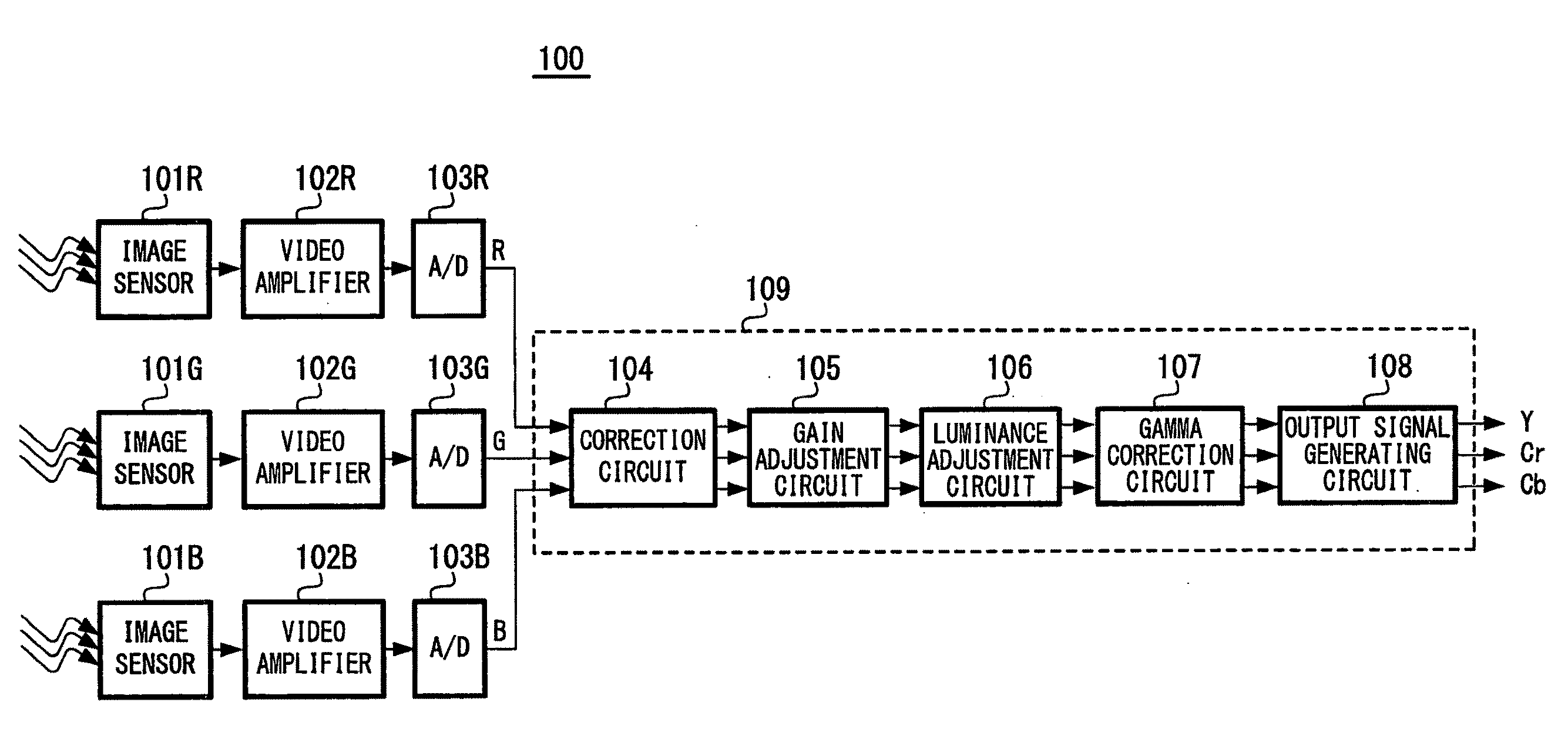
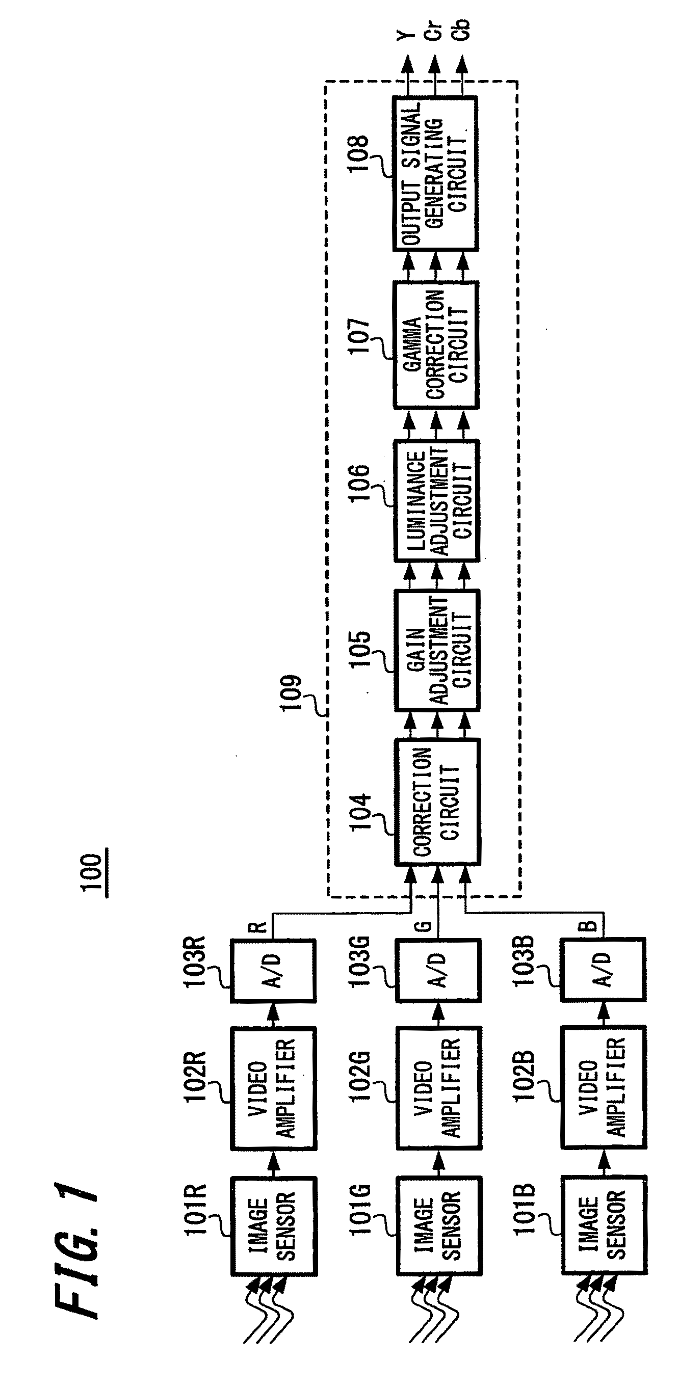
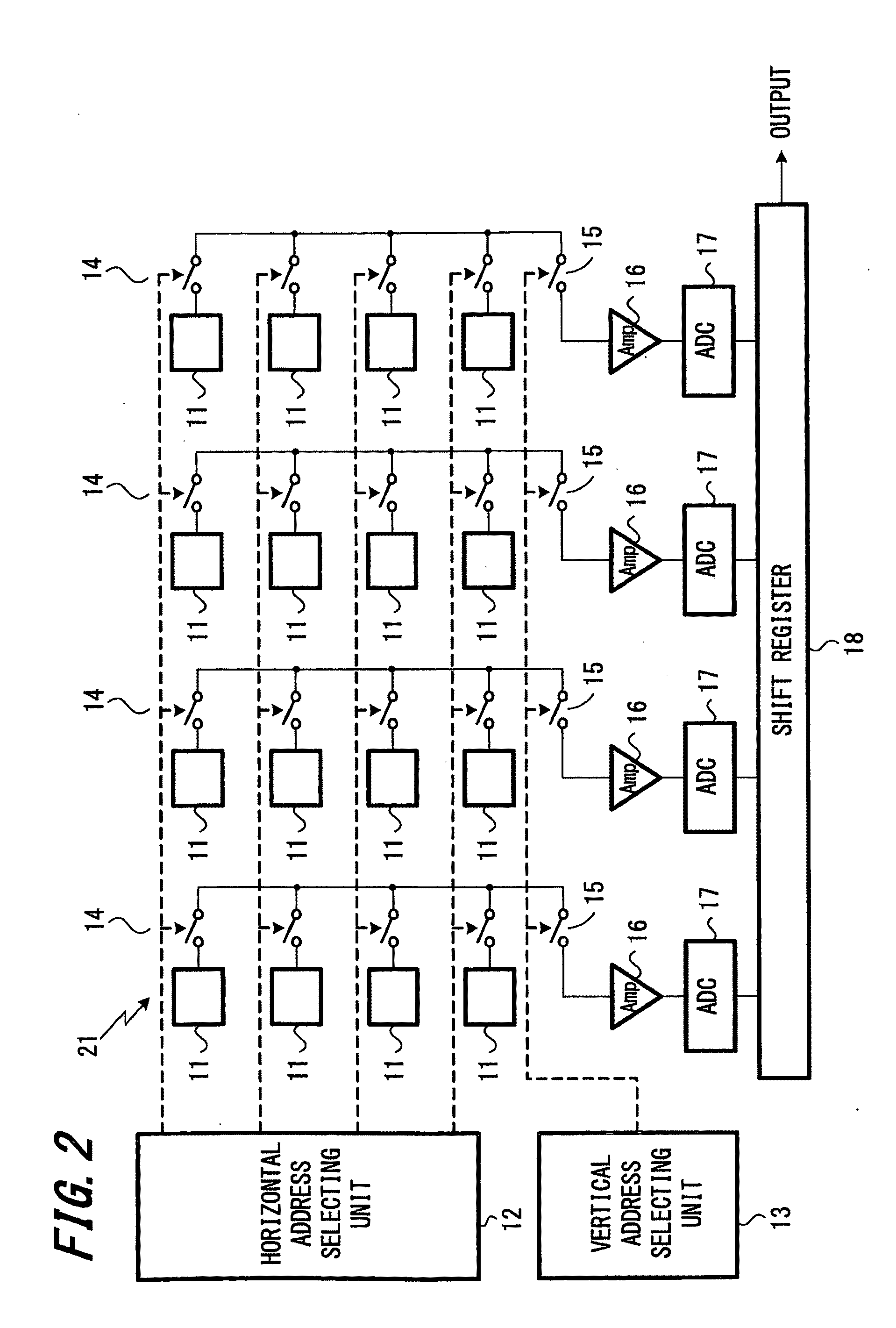
[0032]the present invention will be described with reference to FIGS. 1 to 9. FIG. 1 is a diagram showing the overall configuration of an imaging apparatus 100 according to an embodiment of the present invention. The imaging apparatus 100 is a three-sensor color imaging apparatus where a separate image sensor is provided for each color. That is, the imaging apparatus 100 includes image sensors 101R, 101G, and 101B. The image sensors 101R, 101G, and 101B are image sensors that capture images of red, green, and blue, respectively. In the present embodiment, CMOS image sensors are used as the image sensors. A specific example configuration of a CMOS image sensor will be described later. The image signals captured and output by the image sensors 101R, 101G, and 101B are amplified to an appropriate level by video amplifiers 102R, 102G, and 102B and are then converted to digital data R, G, and B for the respective colors by analog / digital converters 103R, 103G, and 103B. The converted dat...

second embodiment

[0060]An imaging apparatus has an overall configuration similar to the above-described imaging apparatus 100 shown in FIG. 1. As the image sensors 101R, 101G, and 101B provided in the imaging apparatus 100, it is possible to use various types of sensors such as CMOS image sensors and CCD image sensors. One type of correction processing carried out by the correction circuit 104 in the imaging apparatus 100 is correction of streaking, i.e., correction of errors in the horizontal direction. During streaking correction, it is preferable to detect and correct streaking amounts in image signals before adjustment of gain.

[0061]Streaking correction is carried out by detecting streaking amounts from shielded parts of the image sensor, generating correction amounts, and subtracting the generated correction amounts from the original signals.

[0062]FIG. 10 is a diagram showing an example configuration that carries out streaking correction according to the present embodiment. As shown in FIG. 10...


PUM


Abstract

A noise correction circuit that detects and corrects noise included in an image signal output from an image sensor is provided. The noise correction circuit includes a noise determining unit, a noise removing unit, and a random number adding unit. The noise determining unit is configured to calculate an average value of a signal level in a predetermined range of the image signal output from the image sensor and use the calculated average value to calculate a noise component in a predetermined direction. The noise removing unit is configured to remove noise from the image signal output from the image sensor in response to the noise component determined by the noise determining unit. The random number adding unit is configured to add a random number at a level not determined by quantization of the image signal to the image signal after removal of the noise by the noise removing unit.

Description

CROSS REFERENCES TO RELATED APPLICATIONS[0001]The present invention contains subject matter related to Japanese Patent Application JP 2007-274496 filed in the Japanese Patent Office on Oct. 22, 2007, the entire contents of which being incorporated herein by reference.BACKGROUND OF THE INVENTION[0002]1. Field of the Invention[0003]The present invention relates to a fixed pattern noise correction circuit that removes noise included in an image signal output from an image sensor, to an imaging apparatus including such fixed pattern noise correction circuit, and to a fixed pattern noise correction method applied to an imaging apparatus.[0004]2. Description of the Related Art[0005]In the past, a variety of solid-state imaging apparatuses that use a sensor such as a CMOS (Complementary Metal Oxide Semiconductor) image sensor or a CCD (Charge Coupled Device) image sensor have been developed and commercialized. Such solid-state imaging apparatuses may have fixed pattern noise that is presen...

Claims


Application Information

Patent Timeline
IPC IPC(8): G06K9/40H04N5/335H04N5/365H04N5/374H04N5/378H04N9/04
CPCH04N5/3658H04N9/09H04N9/045H04N25/677H04N23/84H04N23/13
Inventor TAKAHASHI, KAZUSHIGEIKEYAMA, HIROMASAHARA, MANABUKINOSHITA, YUKIHIRO
Owner SONY CORP
Why Eureka
Try Eureka