Reluctance motor and self-control optical coupled switch and motion control, structure damp and radiating method

A technology of reluctance motors and motors, applied in the direction of magnetic circuit shape/style/structure, electronic switches, electric components, etc., can solve the problems of reluctance motor torque ripple, vibration and noise, complex control system, etc., and achieve frequency Effects of self-sufficiency and positioning control, increased mechanical angle width, and simple control system

Inactive Publication Date: 2007-12-19
张玉宝
View PDF0 Cites 12 Cited by
  • Summary
  • Abstract
  • Description
  • Claims
  • Application Information

AI Technical Summary

Problems solved by technology

Because the path of this "short-circuit magnetic flux" tends to be the shortest, but the reluctance cannot be minimized due to the air gap, so the compression of the radial air gap is formed, but due to structural reasons, this The force of radial compression ends up being the main source of electromagnetic noise
[0009] (2) Since the reluctance motor belongs to the electric transmission device with continuous operation, during the continuous shut-off and switching process of the phase winding current, due to the short-term overlapping energization phenomenon between the adjacent stator windings, the adjacent stator windings Vibration and noise are generated due to the same polarity of the magnetomotive force and mutual repulsion
[0010] (3) Because the reluctance motor of the prior art has two kinds of mutation factors, the stepped air gap and the use of switching power supply, on the variable reluctance circuit of the stator and rotor, directly lead to the torque ripple of the reluctance motor, according to At present, with this structure, it is almost impossible to fundamentally eliminate the torque ripple phenomenon of the reluctance motor.
[0011] In addition, the reluctance motor in the prior art also has the defects of low power per unit volume of the motor and complex control system and high cost due to the too small energization interval of the phase winding.

Method used


Image

  • Reluctance motor and self-control optical coupled switch and motion control, structure damp and radiating method
  • Reluctance motor and self-control optical coupled switch and motion control, structure damp and radiating method
  • Reluctance motor and self-control optical coupled switch and motion control, structure damp and radiating method

Examples


Embodiment Construction

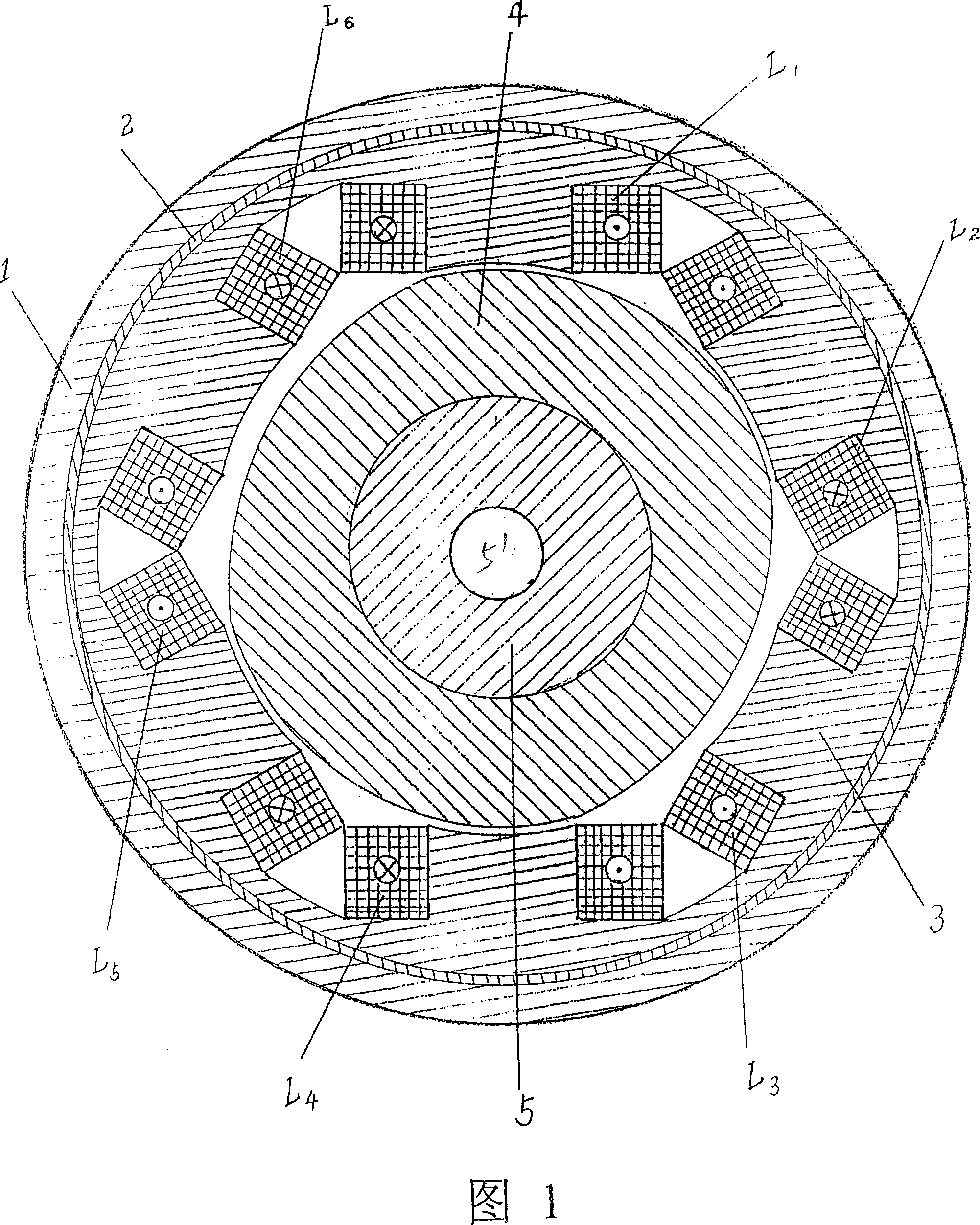
[0040] According to Fig. 1, the reluctance motor of the present invention adopts a three-phase stator structure, that is, six stator poles are distributed equidistantly on the circumference, and the width of each stator pole is equal to the spacing. A simple concentrated winding is installed on each stator pole, and the windings on the two radially opposite stator poles are connected in series or in parallel to form a phase. That is: the L 1 and L 4 Form A phase, L 2 and L 5 Form B phase, L 3 and L 6 To form the C phase, the magnetic flux polarity between the adjacent stator poles should be designed to be opposite to each other. Then, the elliptical two-pole rotor core 4 is installed on the hollow rotor shaft 5, and passed through the two ends of the motor. Bearings, end caps (not shown in the figure) are connected and fixed with the machine base 1. The motion mechanism that constitutes the entire motor. Among them, at both ends of the long axis of the elliptical two-po...


PUM


Abstract

This invention discloses a three-phase magnetic resistance motor, which replaces the multi-stage rotor core with a ladder-type convex pole with an ellipse two pole rotor core and utilizes a self-controlled light-coupled switch mounted on the axostyle of the rotor to realize location control and frequency self-support having the character of a self-controlled synchronous motor, and its unit volumepower reaches to over 4 times of the present one.

Description

Technical field: [0001] The present invention relates to a reluctance motor, in particular to the shape of a rotor core used in the reluctance motor. The present invention also relates to the self-controlled optocoupler switch used by the motor, in particular to the movable grating in the self-controlled optocoupler switch, the present invention also relates to the heat dissipation method of the motor rotor, in particular to a motor with automatic ventilation Functional hollow shaft. The invention also relates to motion control of the motor, and a method of increasing structural damping. The invention also relates to a method for the electric motor to be powered by three-phase alternating current rectification. Background technique: [0002] The reluctance motor, as a continuous running electrical transmission, is fundamentally different from the traditional AC and DC motors in its structure and working principle. This kind of motor does not rely on the interaction of the...

Claims


Application Information

Patent Timeline
Patent Type & Authority Applications(China)
IPC IPC(8): H02K29/06H02K1/24H02K1/14H03K17/94H02P6/22H02K9/00
Inventor 张玉宝
Owner 张玉宝
Why Eureka
Try Eureka