Guidewire and catheter management device

a technology of management device and guidewire, which is applied in the direction of catheters, machine supports, manufacturing tools, etc., can solve the problems of guidewires being inadvertently pulled out of the vessel, the catheter is bulky and difficult to control, and the accuracy of the associated device is hindered, so as to achieve easy insertion and removal

Active Publication Date: 2013-09-03
TELEFLEX LIFE SCI LTD
View PDF46 Cites 31 Cited by
  • Summary
  • Abstract
  • Description
  • Claims
  • Application Information

AI Technical Summary

Benefits of technology

[0013]One system provides a small, firm but pliable pad that can lie on the surgical field, separated from the Y adaptor. The pad can be attached to drapes or some other item in the surgical field, such as by clamping, so as to maintain its desired position relative to the Y adaptor. The pad typically has between two and four pairs of grooves or clamps on it, adapted to hold in place two to four associated pairs of flexible elongated members, with each associated pair of flexible elongated members typically consisting of a guidewire and a catheter. The flexible elongated members in each pair are said herein to be “associated” with each other because the guidewire and the catheter are used together. The grooves or clamps can be arranged in a curved layout, so as to “fan out” the wire / catheter pairs and assist in keeping the free ends of each wire / catheter pair separated from the free ends of other pairs. The grooves or clamps are designed to allow easy insertion and removal of the flexible elongated members. Some of the grooves or clamps can be designed to securely hold a wire or catheter against axial movement, while others can be designed to simply hold a wire or catheter in place relative to the other pairs, without restricting the axial movement of the wire or catheter being held.
[0017]In one implementation, the housing includes a number of vertical supports between which are mounted at least one retaining member housing. The retaining member housing may in turn house a retaining member, suitable for receiving and retaining an elongated device such as a catheter or guidewire. The retaining member may have a suitable size, shape, and level of flexibility to allow a catheter or guidewire to be placed therein and held with a desired level of force until a user desires to remove the catheter or guidewire. The retaining member may include one or more slots or grooves for retaining one or more catheters and / or guidewires. Using the device, catheter / guidewire combinations or other such paired devices, or indeed any devices, may be effectively managed in a surgical field.

Problems solved by technology

Further, different devices, such as stents, are typically passed over the guidewires on the catheters; therefore, if the wire / catheter pairs become twisted with each other, accurate advancement of the associated devices is hindered.
However, towels are bulky and difficult to control.
Towels securing guidewires also lie on the operative field and if the Y adaptor is moved, the towels tend to stay in place, so that the guidewires may be inadvertently pulled out of the vessel.
The cause of this problem is that the various wire / catheter pairs exit through the same port in the Y adaptor, and that their free ends are more or less free to lie along somewhat parallel paths on the surgical field, hindering adequate identification, control, or organization.

Method used


Image

  • Guidewire and catheter management device
  • Guidewire and catheter management device
  • Guidewire and catheter management device

Examples


first embodiment

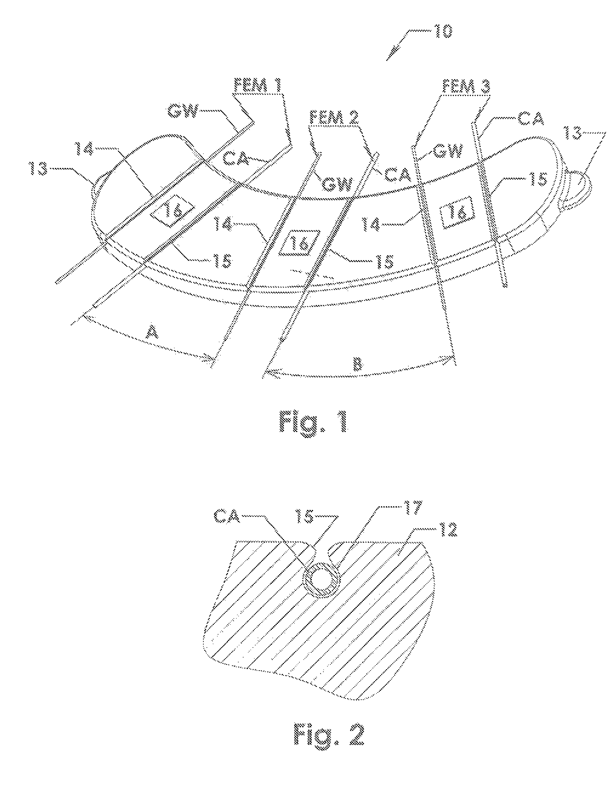
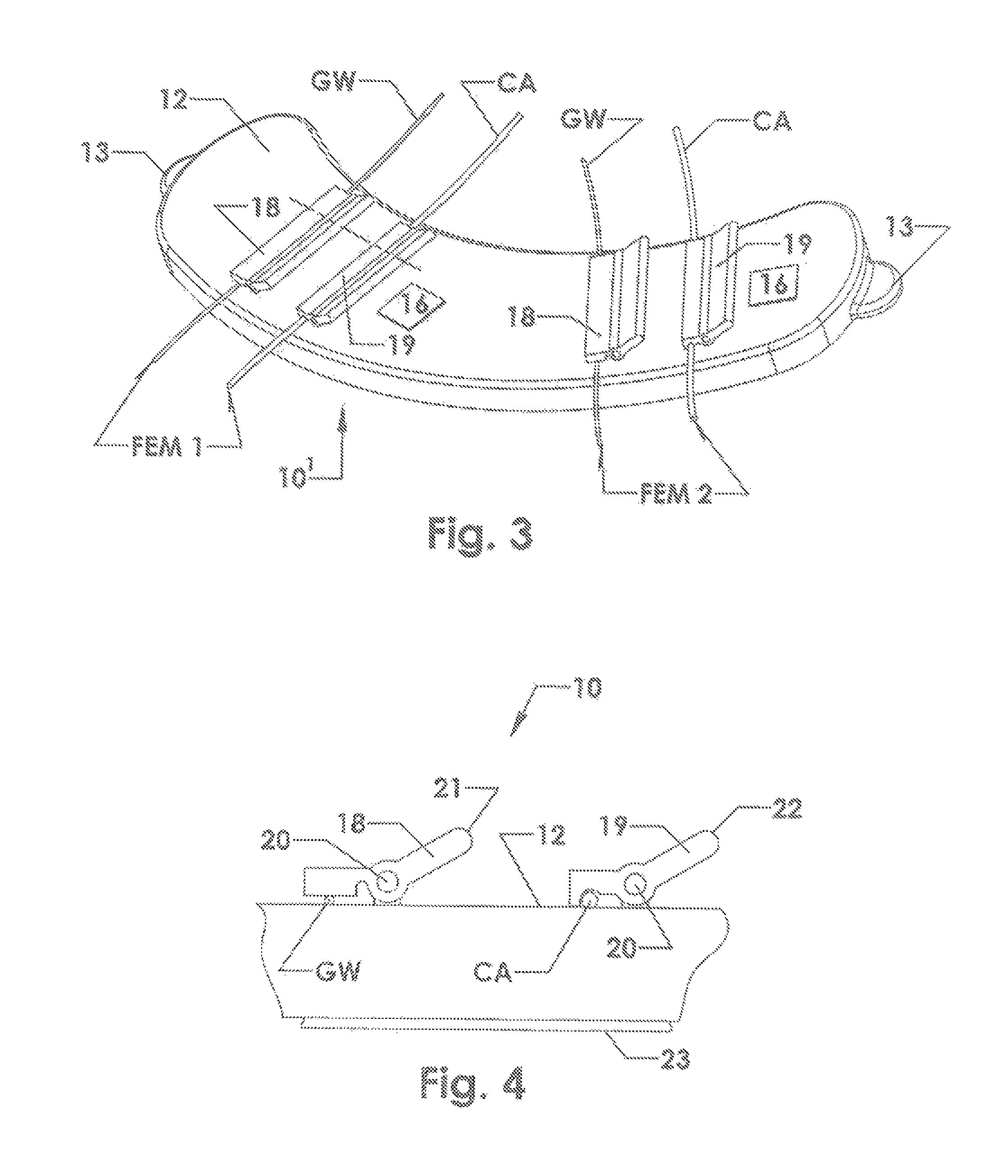
[0036]As shown in FIG. 1, the device 10 of the present invention includes a pad 12 with a plurality of pairs of grooves 14, 15 in its upper surface. Alternatively, the grooves 14, 15 could be formed in a body of flexible material that is mounted on the pad 12. The pad 12 is constructed of a firm but flexible material. Two or more flat tabs 13 can be formed on the pad 12, to provide surfaces to which surgical clamps can be attached, to hold the pad 12 on a surgical drape, in a selected position and orientation relative to a Y adaptor. Each pair of grooves 14, 15 has an associated label 16, identifying the guidewire GW and the catheter CA that are secured in the respective groove pair. A first pair of flexible elongated members FEM1 can be secured in a first pair of grooves 14, 15, near one end of the pad 12, with a guidewire GW in a first groove 14 and a catheter CA in a second groove 15. Similarly, a second pair of flexible elongated members FEM2 can be secured in a second pair of g...

fifth embodiment

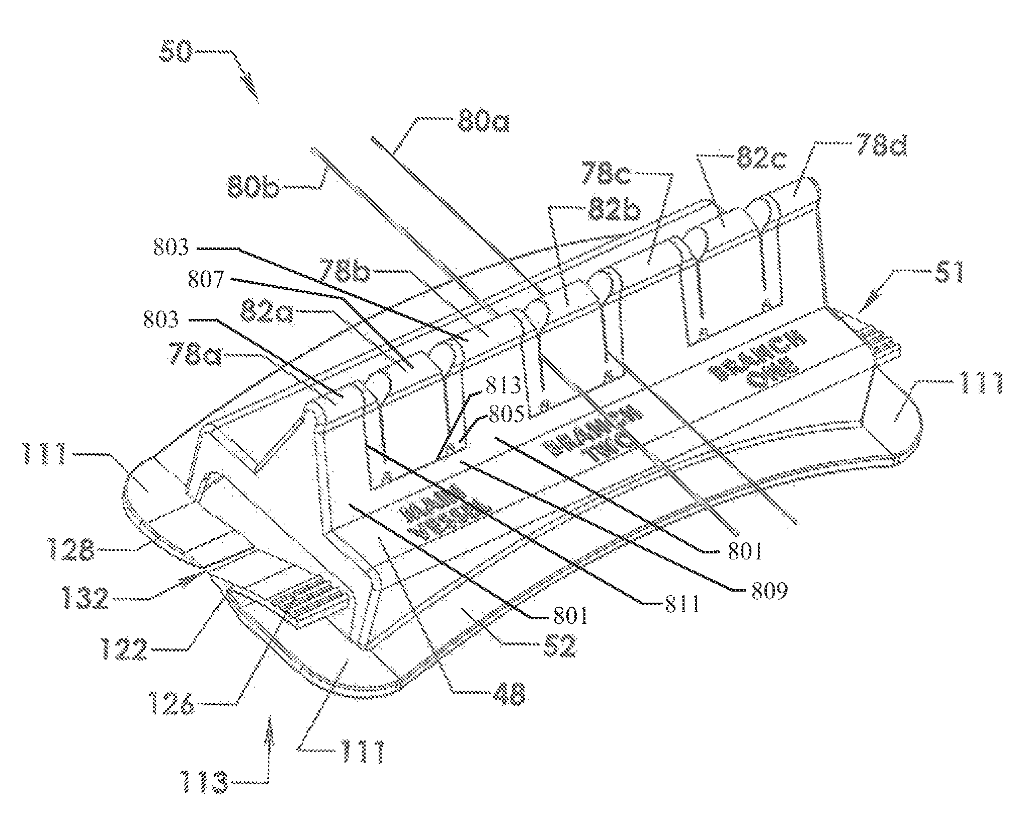
[0066]In this fifth embodiment, the device 60 has a housing 61 with a top surface 48 from which extend vertically upward a number of supports 54a, 54b, etc. A number of retaining member housings 44a-44c are illustrated as mounted in the housing 61. A number of retaining members 46a-46f are illustrated mounted in the retaining member housings. In many cases, the retaining member housings may be formed integrally with the housing 61. As shown in FIG. 7(C), the retaining members 46i may be inserted into the retaining member housings via snap-fit components 47 (shown in FIG. 7(F)). Also as shown in FIG. 7(F), the retaining members may be formed using the open mold process described above in connection with FIG. 5(E), with the benefits appertaining thereto. FIG. 7(F) also illustrates details of the slot and groove which are generally the same as described above in connection with FIGS. 6(C)-6(E), are given corresponding (and primed) reference numerals, and are thus not further described ...

sixth embodiment

[0067]FIGS. 8(A)-8(E) illustrate a number of views of a device 60′ for catheter and guidewire management, having a housing 90 with vertical supports 91a-91g. In this device 60′, retaining members 67a-67f with ribbed slots or grooves are employed. Certain elements are similar to those described above with respect to FIGS. 6(A)-6(E), and these elements have been given the same reference numerals and are not further described here.

[0068]Details of the ribbed retaining members 67i are shown in FIGS. 8(E)-8(G). The retaining member 67i includes fingers 72a and 72b. The finger 72a includes a rib 74a and an indentation 76a, while the finger 72b is shown with a rib 74b and an indentation76b. The rib 74a fits into the indentation 76b while the rib 74b fits into the indentation 76a. In this way, a catheter or guidewire may be held even more securely, while minimizing the effects of “healing”, described in greater detail below. Such retaining members 67i may be conveniently manufactured using ...


PUM

PropertyMeasurementUnit
Shore hardnessaaaaaaaaaa
angleaaaaaaaaaa
angleaaaaaaaaaa

Abstract

Provided are devices and methods for catheter and guidewire management in a surgical setting. In one implementation, the device includes a housing having a curved bottom surface for accommodating the shape of a patient's leg. A retaining member is included, which can retain one or more guidewires, catheters, or the like. In another embodiment, the housing may include a number of vertical supports between which are mounted at least one retaining member housing. The retaining member housing may in turn house a retaining member, suitable for receiving and retaining one or more elongated devices such as catheters or guidewires. The retaining member may have a suitable size, shape, and level of flexibility to allow a catheter or guidewire to be placed therein and held with a desired level of force until such a time as a user desires to remove the catheter or guidewire.

Description

CROSS REFERENCE TO RELATED APPLICATIONS[0001]This application is a continuation-in-part of U.S. patent application Ser. No. 12 / 217,852, filed Jul. 8, 2008, entitled “Guide Wire and Catheter Management Device”, the entirety of which is incorporated by reference herein.STATEMENT REGARDING FEDERALLY SPONSORED RESEARCH OR DEVELOPMENT[0002]Not ApplicableBACKGROUND OF THE INVENTION[0003]1. Field of the Invention[0004]This invention is in the field of equipment used for intravascular medical procedures, specifically flexible elongated members such as guidewires and catheters that are introduced into a patient's blood vessel.[0005]2. Background Art[0006]Invasive vascular procedures like balloon angioplasty and stent implantation require insertion of a guide catheter into the vasculature, usually in the femoral (leg) artery and directing the catheter to the vasculature in need of treatment, such as the heart. Through this catheter, a thin (for example 0.014 inch) wire called a guidewire, is ...

Claims


Application Information

Patent Timeline
Patent Type & Authority Patents(United States)
IPC IPC(8): A61M5/32
CPCA61M25/02A61M2025/024A61M2025/0266A61M2025/028
Inventor TEIRSTEIN, PAUL S.ATKINSON, WILLIAMGOULD, WILLIAMCHIN, YEMSCOPTON, PAULCARMICHAEL, JR., ROBERT F.
Owner TELEFLEX LIFE SCI LTD
Why Eureka
Try Eureka