Expandable slide and lock stent

a technology of stents and slides, applied in the field of expandable medical implants, can solve the problems of mechanical and vasodynamic limitations of stents, limitations related to deployment, and limitations related to vasodynamic capabilities

Inactive Publication Date: 2013-09-03
REVA MEDICAL
View PDF459 Cites 71 Cited by
  • Summary
  • Abstract
  • Description
  • Claims
  • Application Information

AI Technical Summary

Benefits of technology

[0012]Further, in accordance with some embodiments is the realization that the shape and structure of a stent can impact whether the stent undergoes a twisting or rotation about a longitudinal axis of the stent during deployment. In certain instances, it can be advantageous to reduce or minimize the twisting of a stent during expansion, e.g., to facilitate expansion of the stent by reducing friction between components of the stent and / or between the stent and the vasculature. For example, the stent can include a longitudinally-extending structure (e.g., a backbone or backbone member) that can extend at least partially (e.g. helically) around a circumference of the stent. In some cases, such a configuration can promote deployment, provide torsional flexibility, and reduce twisting of the stent. As disclosed herein, embodiments are disclosed herein that enable such a configuration to not only provide portable flexibility, but to also provide reduced binding of the stent during deployment.
[0051]In some embodiments, the undulating helical backbone can comprise portions of reduced thickness for allowing at least partial nesting of an elongate rib element thereagainst. Further, a pair of elongate rib elements can be interconnected at their distal portions by a crossbar. The crossbar can comprise an offset portion configured to at least partially receive an elongate rib of an adjacent radial element for reducing a passing profile of a stent formed using a plurality of radial elements. Next, the undulating helical backbone can extend helically at a generally fixed radius and helix angle relative to the longitudinal axis. The engagement slot can comprise a through slot that defines a central axis extending in a generally circumferential direction and within a plane that is perpendicular to the longitudinal axis of the radial element, the central axis of the engagement slot can extend at a non-perpendicular angle relative to the helical backbone.

Problems solved by technology

Although promising candidates for use as implantable devices and device components, these known radially expandable and slidably engaged stents have mechanical and vasodynamic limitations of which the inventors of the present application set out to address.
These limitations can be characterized as deployment related limitations, and limitations related to vasodynamic capabilities.
Intravascular space; especially that of a patient in need of a vascular implant, is generally inconsistent and varies upon the individual with respect to curvature, plaque buildup and other luminary obstructions.
Furthermore, the shape and structure of the stent may impact the rate and order that discrete areas of the stent deploy, e.g., expand.
Such inconsistent and / or non-uniform deployment may render deployment and placement of prior art stents more difficult and less predictable.
However, even after such procedures, vascular characteristics remain patient delineated and largely inconsistent.
Further, in accordance with at least some embodiments disclosed herein is the realization that a helical stent can often experience binding or deployment problems as the helical arrangement unwinds, which must occur from either or both ends of the helical stent.
These expansion characteristics are unsatisfactory as they provide nonuniform deployment and structural properties.
Such prior art stents exhibited a “critical length” because their length was limited due to the expansion force requirements of the stent and the expansion force limitations of the catheter balloon.
Above a certain size, some balloons were not strong enough to properly deploy such stents.
In particular, a helical stent might create undue stress on the balloon toward the center of the stent due to the binding problems discussed above.

Method used


Image

  • Expandable slide and lock stent
  • Expandable slide and lock stent
  • Expandable slide and lock stent

Examples


examples

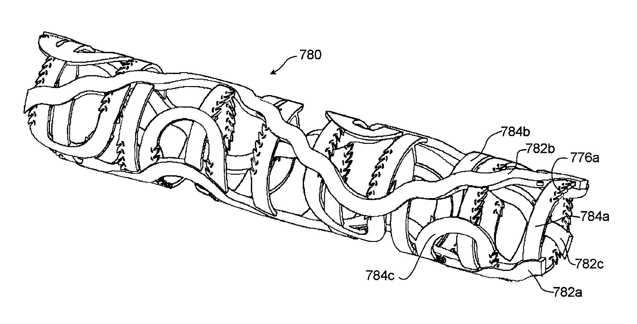
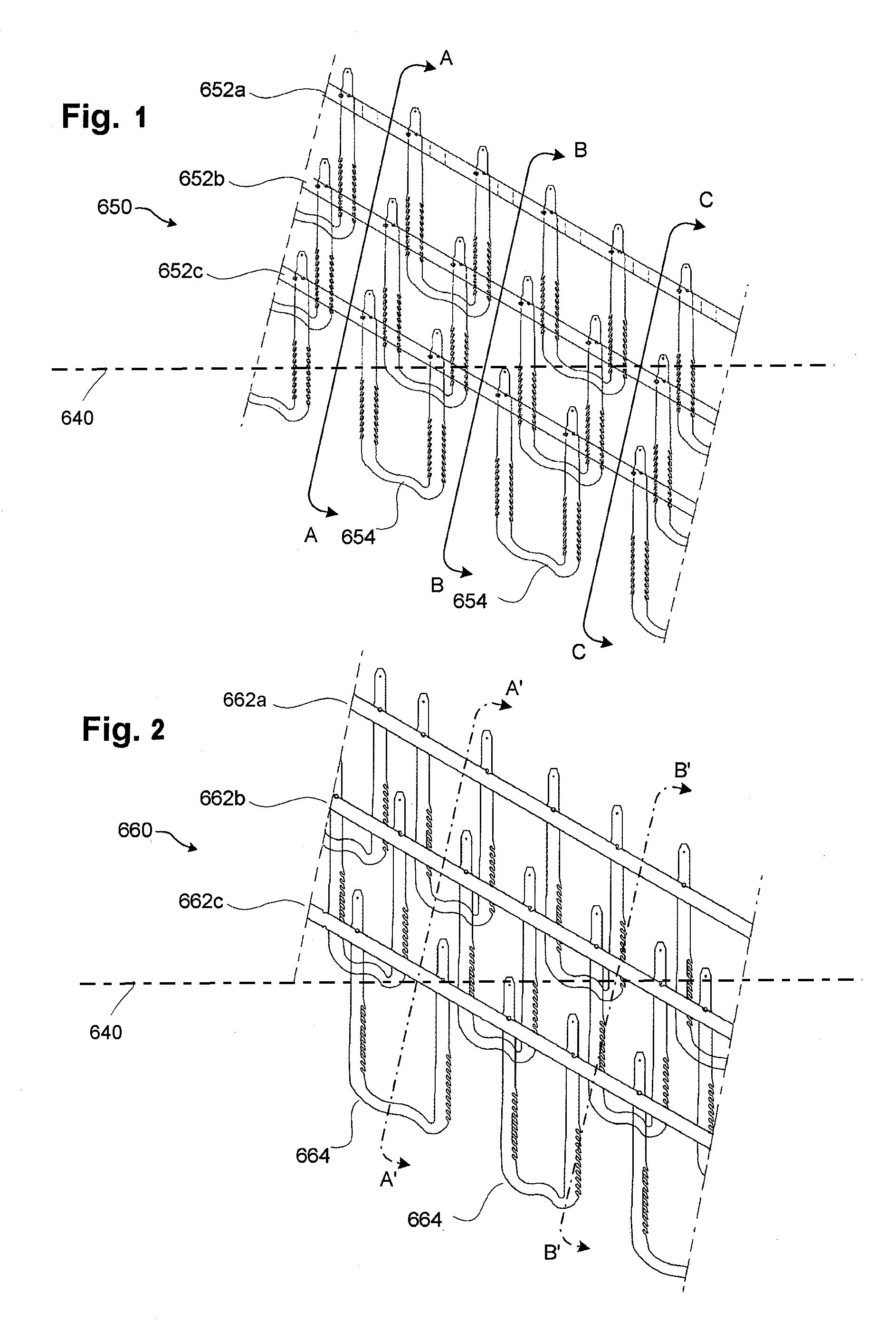
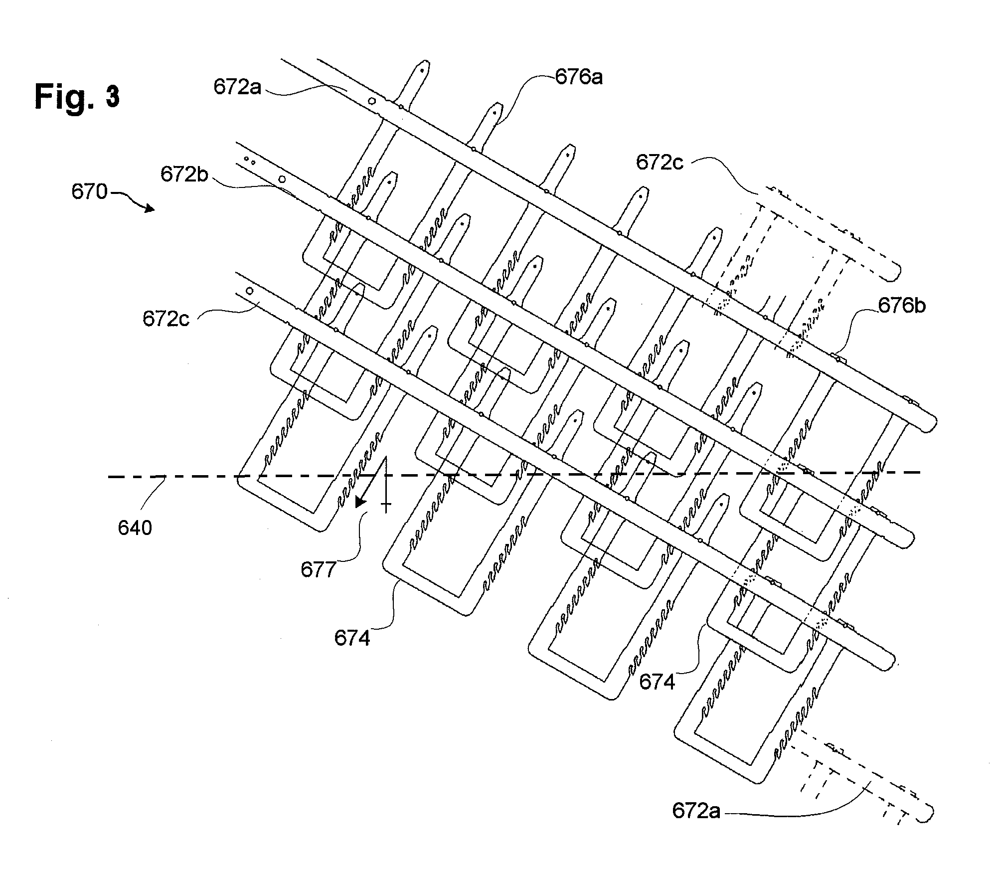
[0132]FIGS. 1-20D illustrate examples of stent embodiments having aspects of the embodiments disclosed herein. For clarity of the stent structure, certain of these figures illustrate various stent embodiments in a flat (e.g., unrolled) state. It should be understood, however, that such for delivery and / or implantation in a vascular structure, such embodiments can be rolled to form a tubular member. Although parts of the stent may have been illustrated as being on opposite sides of the stent (see, e.g., FIG. 9A, elements 732a and 735) for clarity, in the rolled state such elements can be slidingly engaged (see, e.g., FIG. 9C). Various figures include a representation of a longitudinal axis 640 of a stent if formed into a tubular member. The longitudinal axis 640 can provide a frame of reference in measuring relative angles and orientations of components of the stents disclosed herein. However, the longitudinal axis 640 may not in all figures represent a center axis of the stent, but ...


PUM

PropertyMeasurementUnit
angleaaaaaaaaaa
angleaaaaaaaaaa
slot angleaaaaaaaaaa

Abstract

An expandable slide and lock stent comprises a tubular member that can be expanded from a collapsed state to an expanded state. The tubular member can comprise a reversing helical backbone and at least one rail member extending from the helical backbone in a circumferential direction. The backbone can have at least one engagement element that can be configured to receive a rail member to form the tubular member. In some embodiments, the reversing helical backbone can comprise a plurality of discrete segments having a variable profile and / or wave form.

Description

CROSS-REFERENCE TO RELATED APPLICATIONS[0001]This application claims from the benefit of U.S. Provisional Application No. 61 / 322,843, filed Apr. 10, 2010, titled “EXPANDABLE SLIDE AND LOCK STENT,” the entirety of which is incorporated herein by reference.BACKGROUND[0002]1. Field[0003]The present disclosures relate generally to expandable medical implants for maintaining support of a body lumen, and more specifically, to a uniform stent having improved mechanical and post-deployment dynamic capabilities.[0004]2. Description of the Related Art[0005]Various embodiments of vascular implants; such as stents, thrombus filters, and heart valves, are used in their various embodiments for medical applications. Of these vascular devices, one of the leading candidates as a stent device and structural component is the radially expandable and slidably engaged stent as disclosed in commonly owned U.S. Pat. Nos. 6,033,436; 6,224,626; and 6,623,521; the disclosures of which are hereby incorporated ...

Claims


Application Information

Patent Timeline
Patent Type & Authority Patents(United States)
IPC IPC(8): A61F2/06
CPCA61F2/88A61F2/885A61F2/915A61F2/93A61F2/90Y10T29/49826A61F2220/0016A61F2220/005A61F2220/0058A61F2002/91591B33Y80/00A61F2002/825A61F2/844A61F2/89A61F2/92A61F2/86
Inventor SCHMID, ERICWEIER, KEITHESSER, KEITH A.HOWARD, STEVEN C.HOBSON, JOHNBONSIGNORE, CRAIG
Owner REVA MEDICAL
Why Eureka
Try Eureka