Impact energy attenuation system

a technology of impact energy and attenuation system, which is applied in the field can solve the problems of prior art helmet protection system, insufficient protection, and significant problems of prior art system, and achieve the effects of increasing the range of impact energy attenuation, high responsiveness, and rapid res

Active Publication Date: 2013-09-03
9 LIVES SF LLC
View PDF105 Cites 35 Cited by
  • Summary
  • Abstract
  • Description
  • Claims
  • Application Information

AI Technical Summary

Benefits of technology

[0025]The present invention preserves the advantages of prior art impact energy attenuation materials and systems related thereto. In addition, it provides new advantages not found in currently available materials and systems and overcomes many disadvantages of such currently available materials and systems.

Problems solved by technology

As can be well understood, protection of the head is of high concern due to the risk of head trauma and other serious injuries.
Although padding has improved, these prior art systems still have significant problems and suffer from many disadvantages.
One typical shortcoming of prior art helmet protection systems is inadequate protection over a range of impact energies typically encountered in activities they were intended for.
Another typical shortcoming of the prior art is their inability to significantly reduce rotational (off axis) impact energies.
Another typical shortcoming of the prior art is their inability to consistently fit a large range of users head shapes and sizes.
Rigid shell systems are challenged to provide an optimal fit given the range of human head shapes and sizes.
Many prior art helmets use pads of the same thickness throughout and typically result in either loose areas, tight areas or both when fitted to a users head.
Helmets that use foam pad systems, for example, may have areas that fit tightly and since the foam in those areas is overly compressed, impact mitigation is compromised.
Conversely, loose areas do not benefit from additional protection afforded by that dimension.
As a result, they offer little or no ability to establish an optimal fit.
Variable length head bands leave potentially large voids between the band and the shell.
This stored energy in padding systems intended for helmets is generally not preferred because it can cause further trauma to the user.
One disadvantage to these materials is their narrow band of responsiveness to the typical range of impact energies.
Another disadvantage to these materials is their inability to provide an optimal fit for a wide range of user sizes.
One disadvantage to these materials is their slow rate of return to normal once compressed which makes them less suitable to multi-impact applications.
One disadvantage to these materials is the narrow band of responsiveness to impact energies.
Another disadvantage to these materials is the high degree of stored energy they deliver back through the system after an initial impact.
Like rate sensitive materials, one disadvantage to these materials is their slow rate of return to normal once compressed which makes them less suitable to multi-impact applications.
Another disadvantage to these materials is their narrow band or responsiveness to the typical range of impact energies.
One disadvantage to these materials is their reliance on dis-integration, which makes them unsuitable to multi-impact applications.
Another disadvantage to these materials is the difficulty in knowing if they have been compromised or damaged.
One disadvantage to these materials is their inherent capacity to store impact energy and return it to the user's head as a rebound impact.
One disadvantage to these systems is their slow rate of return to normal once compressed which makes them less suitable to multi impact applications.
While virtually all helmets commercially available pass their respective tests, user injuries with different mechanisms of injury persist across the board.
Added weight creates fatigue in the user, but is also known to increase inertia to the head in collisions.
Helmet wearers generally and young sport enthusiasts in particular resist high profile solutions for aesthetic reasons.

Method used


Image

  • Impact energy attenuation system
  • Impact energy attenuation system
  • Impact energy attenuation system

Examples


Embodiment Construction

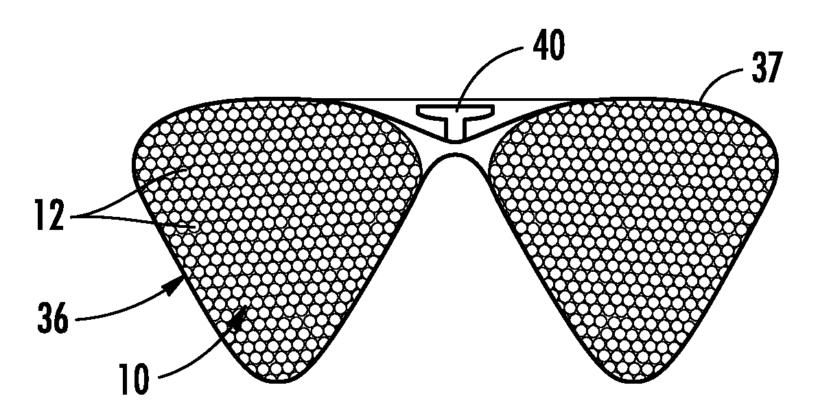
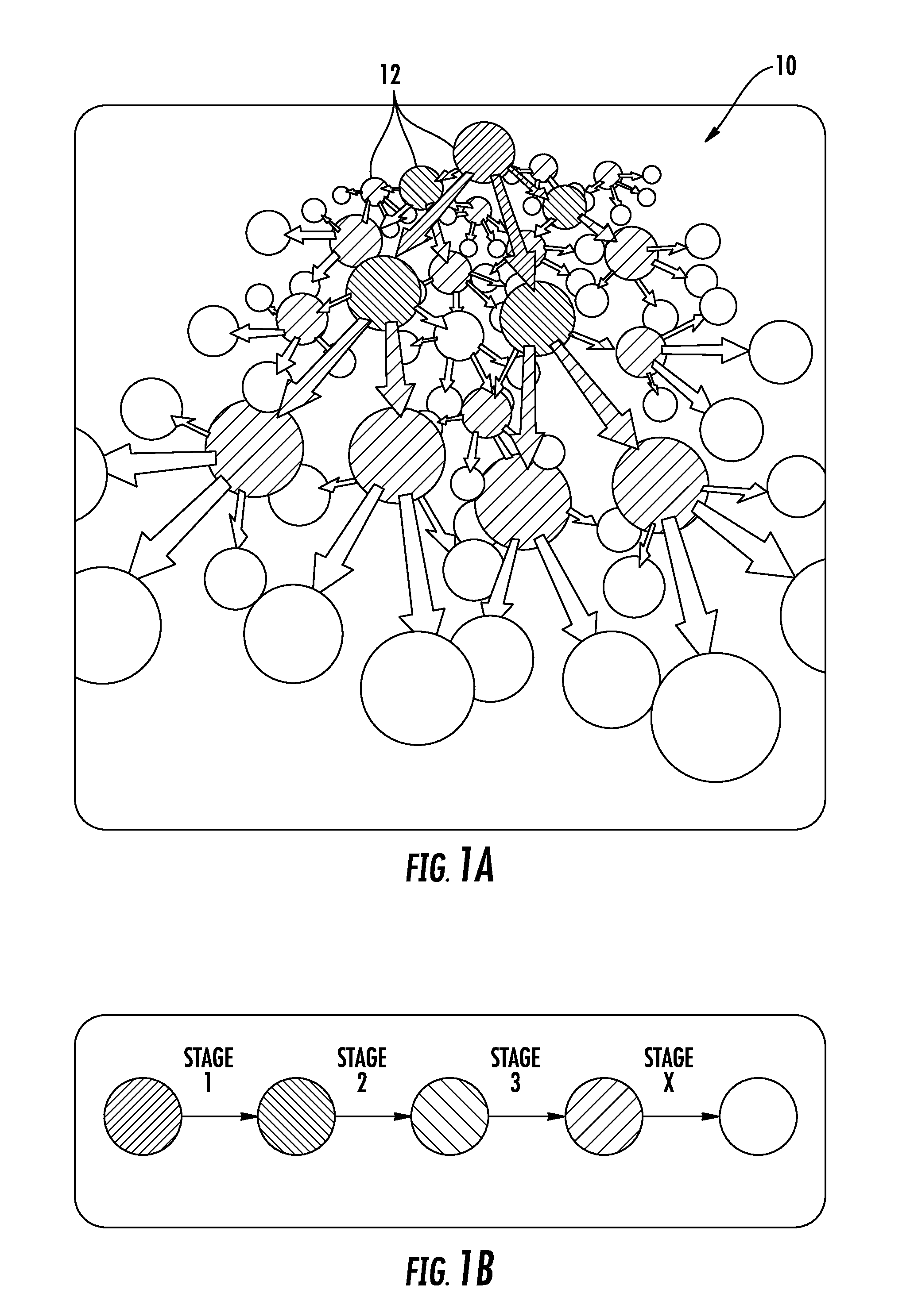
[0083]Turning first to FIG. 1, detail of the impact energy attenuation material 10 of the present invention is shown in detail. Preferably, this material, generally referred to as 10, is made up of a number of discrete particles 12. This loose particle material 10 may be solid plastic beads, hollow plastic beads, glass microspheres and ceramic microspheres. Depending on the application, larger or smaller particles 12 can be used. In a preferred embodiment, the loose particles 12 are preferably approximately 0.1-3 mm diameter spherical elastomeric balls. A mixture of sizes, shapes, and materials for the loose particles 12 is also possible. Further embodiments may include non-spherical particles 12 ranging from oval rounds to hard edged multi-hedron shapes (tetrahedrons, cubes, etc.). In the preferred embodiment, the durometer of the elastomeric particles 12 are preferably in the range of approximately Shore A 10 to approximately Shore A 100.

[0084]The characteristics and performance o...


PUM

PropertyMeasurementUnit
diameteraaaaaaaaaa
time periodaaaaaaaaaa

Abstract

A new and novel impact energy attenuation material, impact energy attenuation module employing the material and a fit system for optimizing the performance thereof is provided. Non-linear energy attenuating material consisting of a plurality of loose particles is employed for impact energy dissipation. The loose particles are preferably spherical elastomeric balls. An impact energy attenuation module includes a container that holds the loose particles. The impact energy attenuation module can be provided in a wide range of sizes and shapes and the loose particles can be provided in different materials, sizes, density, compaction and hardness to suit with the application at hand. A matrix of impact energy attenuation module are provided about the surface of a shell to provide the required impact energy attenuation. The material, impact energy attenuation module and system of the present invention are well suited for protection of body parts and other cushioning and protection needs.

Description

CROSS REFERENCE TO RELATED APPLICATION[0001]This application is related to and claims priority from earlier filed provisional patent application Ser. No. 61 / 261,544, filed Nov. 16, 2009; provisional patent application Ser. No. 61 / 261,568, filed Nov. 16, 2009, provisional patent application Ser. No. 61 / 261,613, filed Nov. 16, 2009 the entire contents of each of the foregoing are incorporated herein by reference.BACKGROUND OF THE INVENTION[0002]The present invention generally relates to impact energy attenuation, and particularly to padding and cushioning systems intended to reduce trauma resulting from impacts to parts of the body, such as the head. Moreover, the present invention relates the general personal protection field, in general, which includes helmets, pads, armor, sports gear, clothing, worker safety equipment, packaging, vehicle interiors, barriers and pads for threat objects, and the like.[0003]The present invention relates to a new and novel way to attenuate impact ener...

Claims


Application Information

Patent Timeline
Patent Type & Authority Patents(United States)
IPC IPC(8): B32B5/16B32B3/02
CPCA41D13/015A42B3/12F16F7/01A42B3/125A41D13/0155Y10T428/2982Y10T428/13A42B3/121
Inventor ANDERSON, ERIK CHRISTIANTURLINGTON, JR., HENRY LEEOEHL, WILHELMKOBE, TIMOTHY MATTHEWGREENWALD, RICHARD MARK
Owner 9 LIVES SF LLC
Why Eureka
Try Eureka