Image processing apparatus and method, and program
a technology of image processing and apparatus, applied in the direction of picture signal generators, instruments, solid-state device signal generators, etc., can solve the problems of increasing computational complexity, and achieve the effect of low computational complexity, small amount of memory
- Summary
- Abstract
- Description
- Claims
- Application Information
AI Technical Summary
Benefits of technology
Problems solved by technology
Method used
Image

Examples
first embodiment
1. First Embodiment
Configuration Example of Digital Video Camera
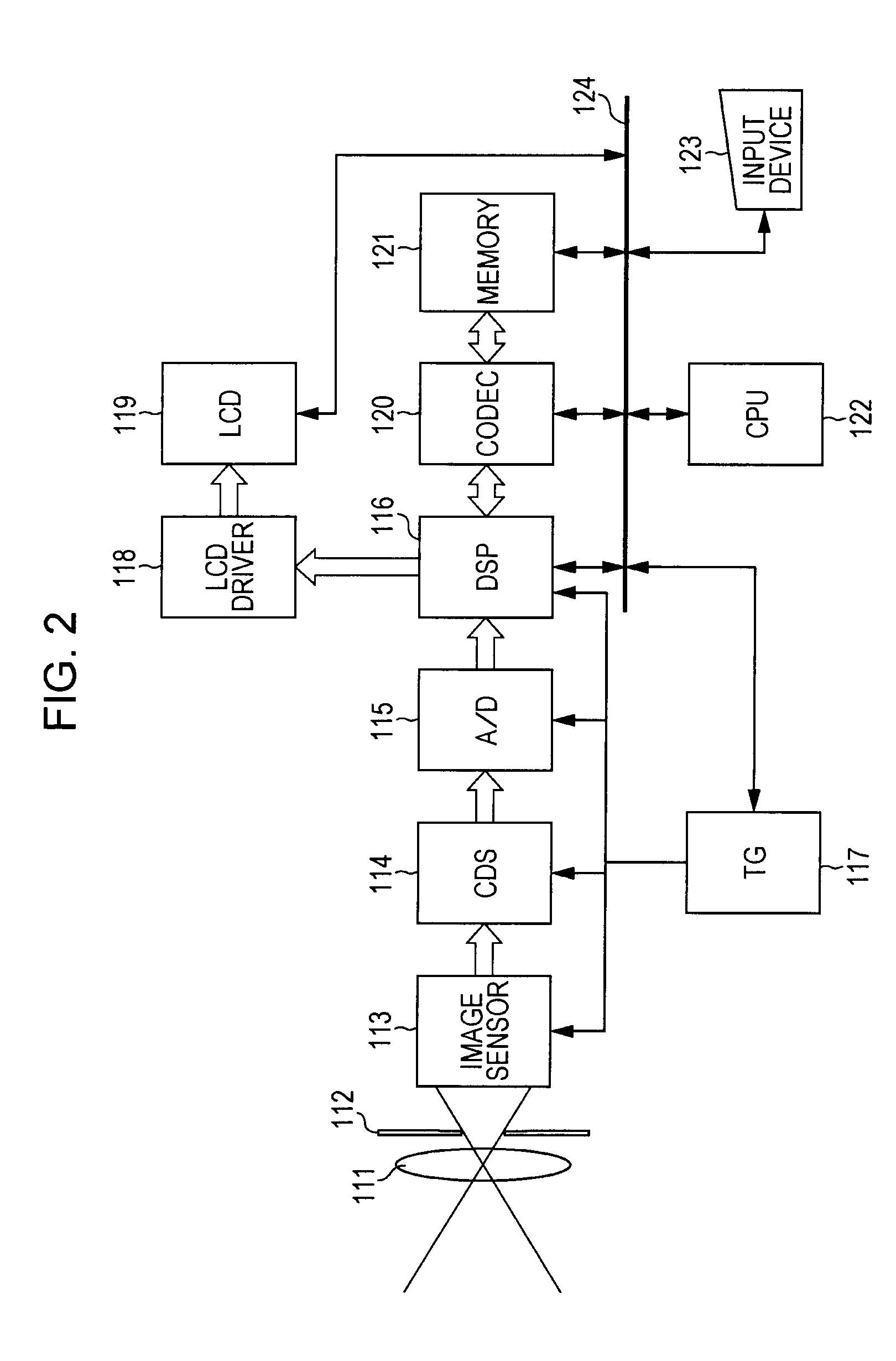
[0062]FIG. 2 is a block diagram showing a digital video camera according to a first embodiment of the present invention. The digital video camera includes a lens 111, a diaphragm 112, an image sensor 113, a correlated double sampling circuit (CDS) 114, an Analog / Digital (A / D) converter 115, a Digital Signal Processor (DSP) block 116, a timing generator (TG) 117, a Liquid Crystal Display (LCD) driver 118, an LCD 119, a Compression / Decompression (CODEC) 120, a memory 121, a Central Processing Unit (CPU) 122, an input device 123, and a bus 124. The DSP block 116 is a block including a signal processor (for example, digital signal processing (DSP)) and a memory such as a Random Access Memory (RAM) for holding image data, a processor executes a predetermined program so as to perform the image processing described below. Hereinafter, the DSP block 116 is referred simply to as the DSP 116.
[0063]Incident light from a subject pa...
second embodiment
2. Second Embodiment
Overview of Second Embodiment
[0184]Next, a second embodiment of the present invention will be described with reference to FIGS. 21 to 24.
[0185]In the second embodiment of the present invention, the computational complexity may be reduced by changing the method of calculating the reference luminance value Lg(nl)(p).
[Configuration Example of Reference Luminance Value Calculation Unit]
[0186]In the digital video camera of the second embodiment of the present invention, instead of the reference luminance value calculation unit 243 of FIG. 10, a reference luminance value calculation unit 243 of FIG. 21 is provided. In FIG. 21, the parts corresponding to FIG. 10 are denoted by the same reference numerals and the description thereof will be appropriately omitted.
[0187]The reference luminance value calculation unit 243 of FIG. 21 includes a primary differential coefficient calculation unit 401, a luminance correction amount calculation unit 402, and a luminance correction...
third embodiment
3. Third Embodiment
Overview of Third Embodiment
[0204]Next, a third embodiment of the present invention will be described with reference to FIGS. 25 to 29.
[0205]In the third embodiment of the present invention, the computational complexity may be reduced by changing the method of calculating the reference luminance value Lg(nl)(p).
[Configuration Example of Reference Luminance Value Calculation Unit]
[0206]In the digital video camera of the third embodiment of the present invention, instead of the reference luminance value calculation unit 243 of FIG. 10, a reference luminance value calculation unit 243 of FIG. 25 is provided. In FIG. 25, the parts corresponding to FIG. 10 are denoted by the same reference numerals and the description thereof will be appropriately omitted.
[0207]The reference luminance value calculation unit 243 of FIG. 25 includes a cumulative histogram calculation unit 501, a cumulative histogram memory 502, an inverse function calculation unit 503, a cumulative histo...
PUM
 Abstract
Description
Claims
Application Information
 - R&D
- Intellectual Property
- Life Sciences
- Materials
- Tech Scout
- Unparalleled Data Quality
- Higher Quality Content
- 60% Fewer Hallucinations
Browse by: Latest US Patents, China's latest patents, Technical Efficacy Thesaurus, Application Domain, Technology Topic, Popular Technical Reports.
© 2025 PatSnap. All rights reserved.Legal|Privacy policy|Modern Slavery Act Transparency Statement|Sitemap|About US| Contact US: help@patsnap.com