
Thermal energy venting system

a venting system and thermal energy technology, applied in ventilation systems, building repairs, heating types, etc., can solve the problems of insufficient venting, inefficient ventilation, and high cost of heating and cooling a building, and achieve the effect of reducing heating/cooling energy expenditure and cos

Active Publication Date: 2013-09-10
ASPENSON MARK A
View PDF20 Cites 47 Cited by
  • Summary
  • Abstract
  • Description
  • Claims
  • Application Information

AI Technical Summary

Benefits of technology

[0008]The thermal energy venting system includes an insulation board disposed in the cavity between adjacent studs and other areas of a domicile or building to form venting channels directing excess heat through a roof vent. The insulation board is a non-porous laminate formed by a rigid foam core covered or sheathed with a reflective facer or plastic. The insulation board provides a thermal barrier for conduction, convection and radiation aspects of thermal energy transfer. The installation of the insulation board forms an envelope that reflects exterior thermal energy and interior thermal energy to maintain comfortable interior temperatures with minimal heating / cooling energy expenditure and costs.

Problems solved by technology

Typical building insulation does not have the capacity to provide the full range of thermal barriers against different sources of thermal energy.
As a consequence, these inefficiencies contribute to the high costs of heating and cooling a building.
In addition to the insulation itself, most homes and buildings do not have adequate venting for dissipating heated air during hot days and retain heated air during the colder months.
This also contributes to higher than necessary costs for heating and cooling.

Method used


Image

  • Thermal energy venting system
  • Thermal energy venting system
  • Thermal energy venting system

Examples


Embodiment Construction

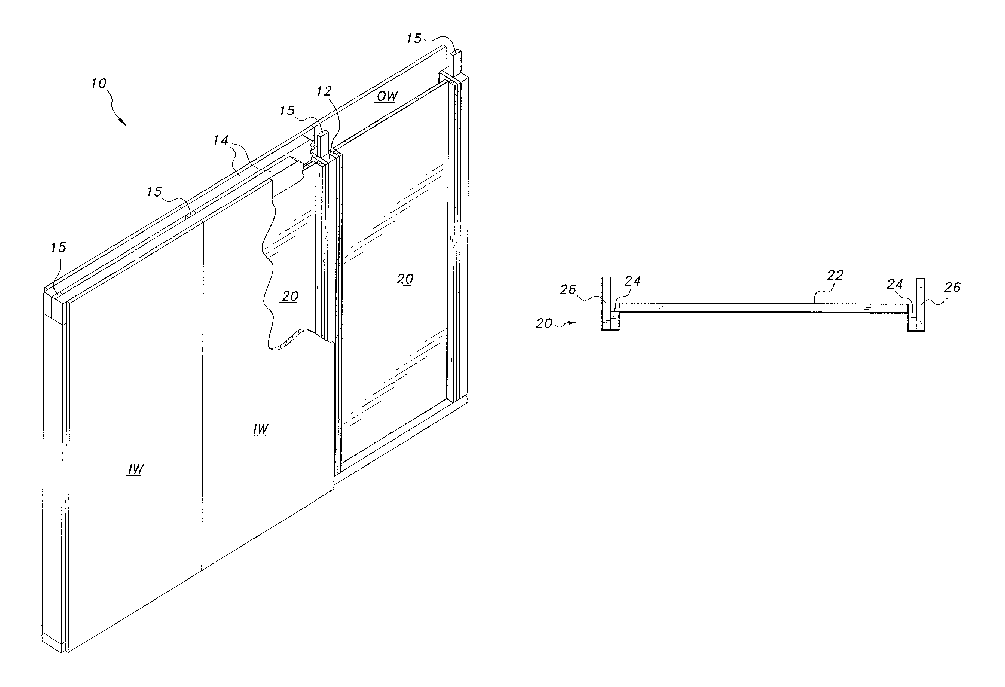
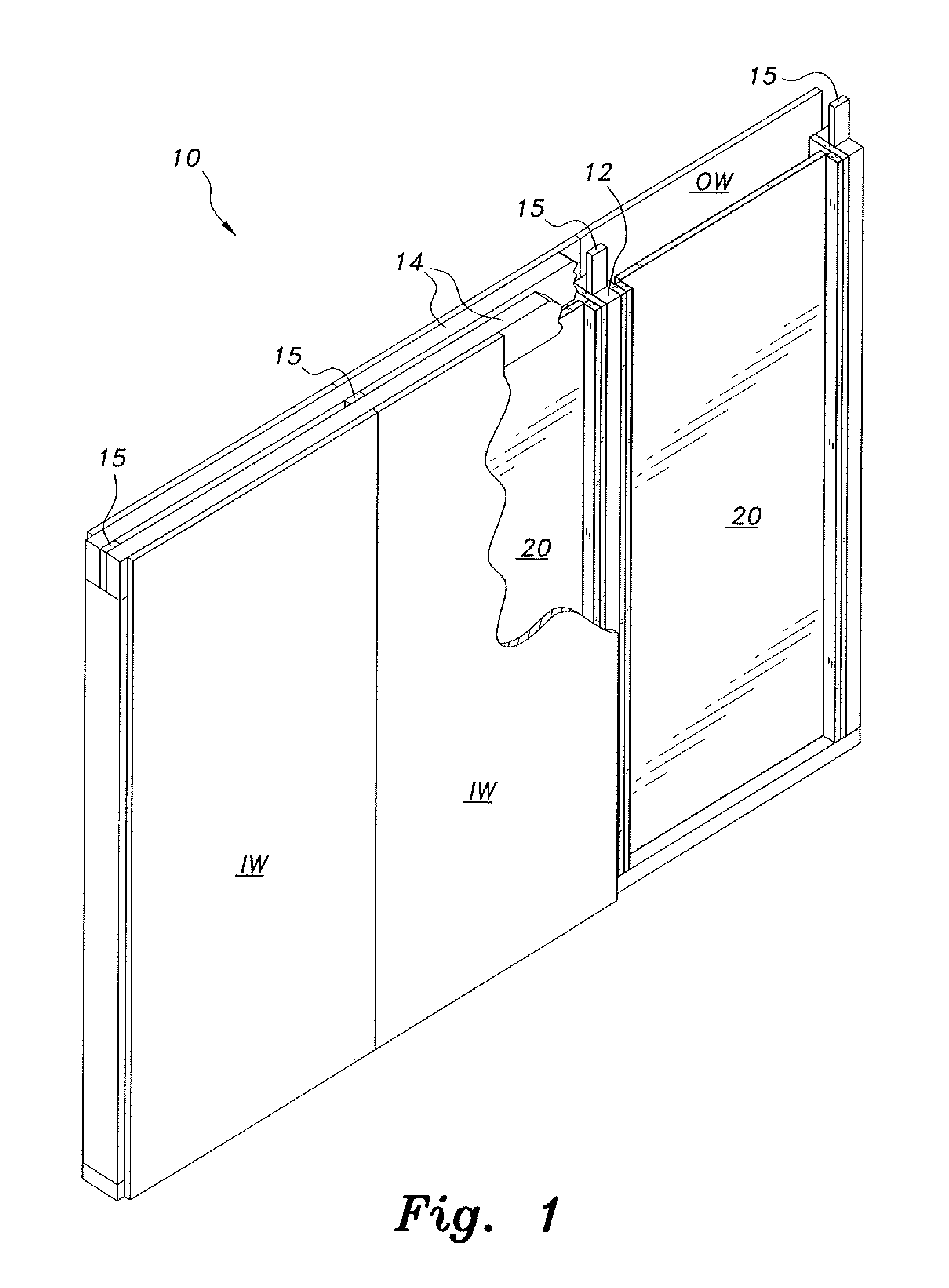
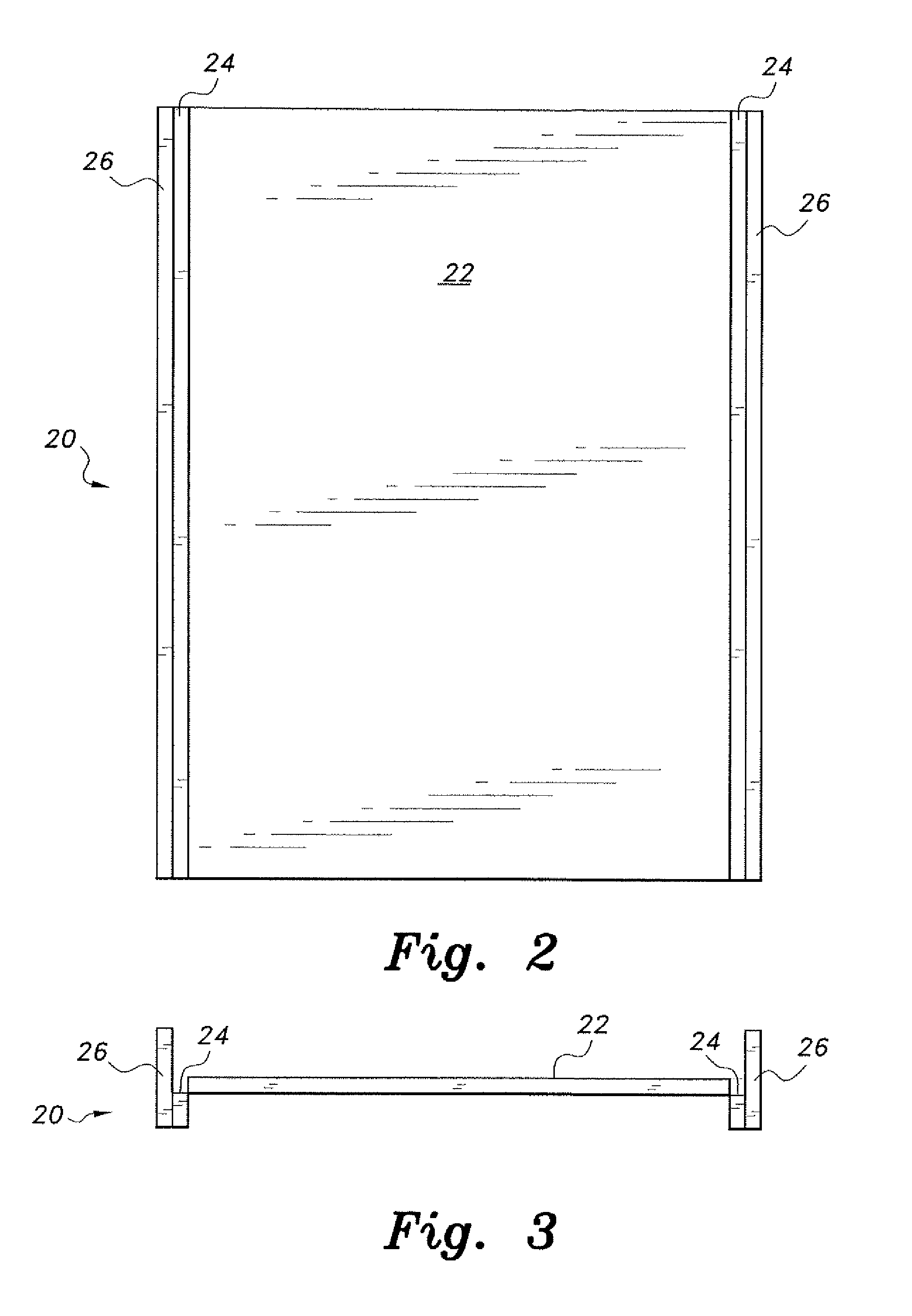
[0018]The thermal energy venting system, generally referred to by reference number 10 in the drawings, provides a thermal break for all three forms of thermal energy and an efficient means of venting thermal energy back out to the environment from a domicile or other building. As shown in FIGS. 1-5, the thermal energy venting system 10 includes a thermal insulation wall, panel or board 20 configured to be mounted between the studs 12 of a wall. The insulation board 20 is designed to form a venting channel between adjacent studs, roof rafters and trusses.

[0019]As shown in FIGS. 2 and 3, the insulation board 20 includes a center panel 22, orthogonally disposed intermediate panels 24 and outer panels 26. In the embodiment shown in the figures, the insulation board 20 is preferably manufactured as a flat board with pre-scored or hot-wired lines adjacent the lateral ends so that the user may fold the lateral ends into the configuration shown in FIG. 3. An example of producing these score...


PUM


Abstract

The thermal energy venting system includes an insulation board disposed in the cavity between adjacent studs and other areas of a domicile or building to form venting channels directing excess heat through a roof / ridge vent. The insulation board is a non-porous laminate formed by a rigid foam core covered or sheathed with a reflective polymeric facer or plastic. The insulation board provides a thermal barrier for conduction, convection and radiation aspects of thermal energy transfer. The installation of the insulation board forms an envelope that reflects exterior thermal energy and interior thermal energy to maintain comfortable interior temperatures with minimal heating / cooling energy expenditure and costs.

Description

CROSS-REFERENCE TO RELATED APPLICATION[0001]This application claims the benefit of U.S. Provisional Patent Application Ser. No. 61 / 522,567, filed Aug. 11, 2011.BACKGROUND OF THE INVENTION[0002]1. Field of the Invention[0003]The present invention relates to building construction systems, and particularly to a thermal energy venting system that provides improved insulation in a building for maintaining more moderate temperatures and reducing energy costs.[0004]2. Description of the Related Art[0005]Typical building insulation does not have the capacity to provide the full range of thermal barriers against different sources of thermal energy. For insulation to perform as well as possible, the insulation should be able to cope with three forms of thermal transfer: conduction, convection and radiation. The national and worldwide R-values for insulation are generally based upon only one form of heat transfer, viz., conduction. However, conduction only represents about 10% of the total the...

Claims


Application Information

Patent Timeline
Patent Type & Authority Patents(United States)
IPC IPC(8): E04B2/28E04B1/78F24F7/04
CPCE04B1/74E04B1/80E04C2/523E04D13/17F24F5/0075F24F7/02E04B2001/7691Y10T428/24231Y02B30/92F24F2005/0082Y10T428/24174Y10T428/24215Y10T428/24264Y02A30/00Y02B30/90
Inventor ASPENSON, MARK A.CONNELL, JOHN G.
Owner ASPENSON MARK A
Learn More