Drilling waste management system

a waste management system and drilling technology, applied in separation processes, centrifuges, borehole/well accessories, etc., can solve the problems of not being able to distinguish shakers, not being able to reuse solids-contaminated drilling fluid, and not being able to separate all the solids from the drilling fluid

Active Publication Date: 2013-09-10
MI
View PDF7 Cites 17 Cited by
  • Summary
  • Abstract
  • Description
  • Claims
  • Application Information

AI Technical Summary

Problems solved by technology

But it is not always possible to separate all the solids from the drilling fluids with a shale shaker.
Additionally, drilling fluids are frequently formulated to contain finely ground solid additives that a shaker cannot distinguish from fine drilling solids, known as low gravity solids.
When shakers alone are insufficient, additional drilling waste management equipment is often used to further separate the solids from the drilling fluid.
Without this additional treatment, the solids-contaminated drilling fluid cannot be re-used and must be discarded.
Unfortunately, existing drilling waste management systems are complicated and expensive to install at the rig site.
The shipping costs, crane rental costs, and labor costs associated with these operations are significant.
In addition to the expenses related to existing drilling waste management systems, the space requirements of these systems are another drawback.
Existing systems need a relatively large amount of space at the rig site.
The equipment itself has a significant footprint.
Also, the cranes and trucks involved in shipping and assembly need additional space to maneuver.
This is a significant drawback because drilling rig sites are becoming smaller and space is at a premium.
There is inherent danger associated with operating cranes, lifting heavy equipment, maneuvering trucks, and installation labor, e.g. welding.
The assembly required by existing drilling waste management systems increases the likelihood that accidents may occur.

Method used


Image

  • Drilling waste management system
  • Drilling waste management system
  • Drilling waste management system

Examples


Embodiment Construction

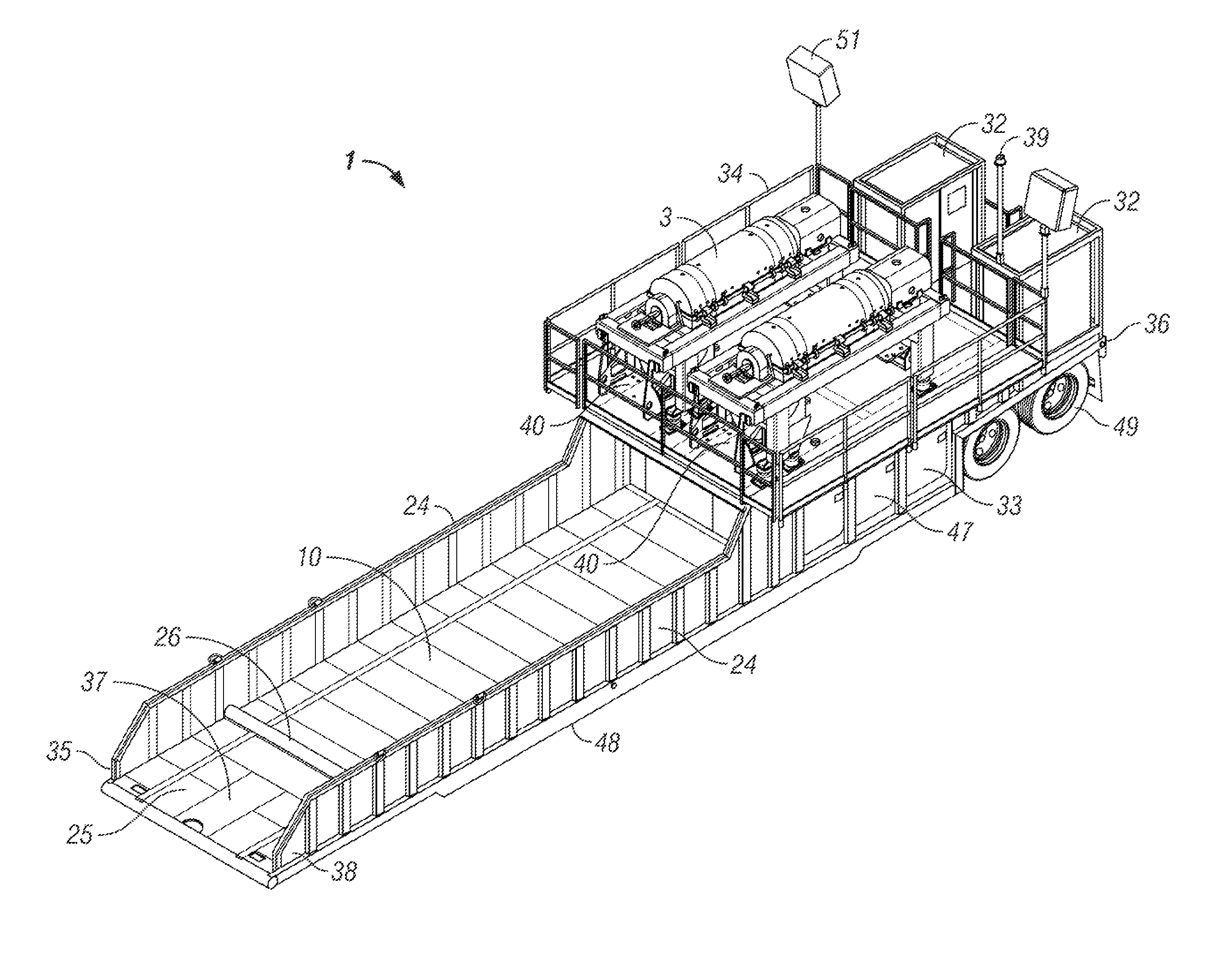
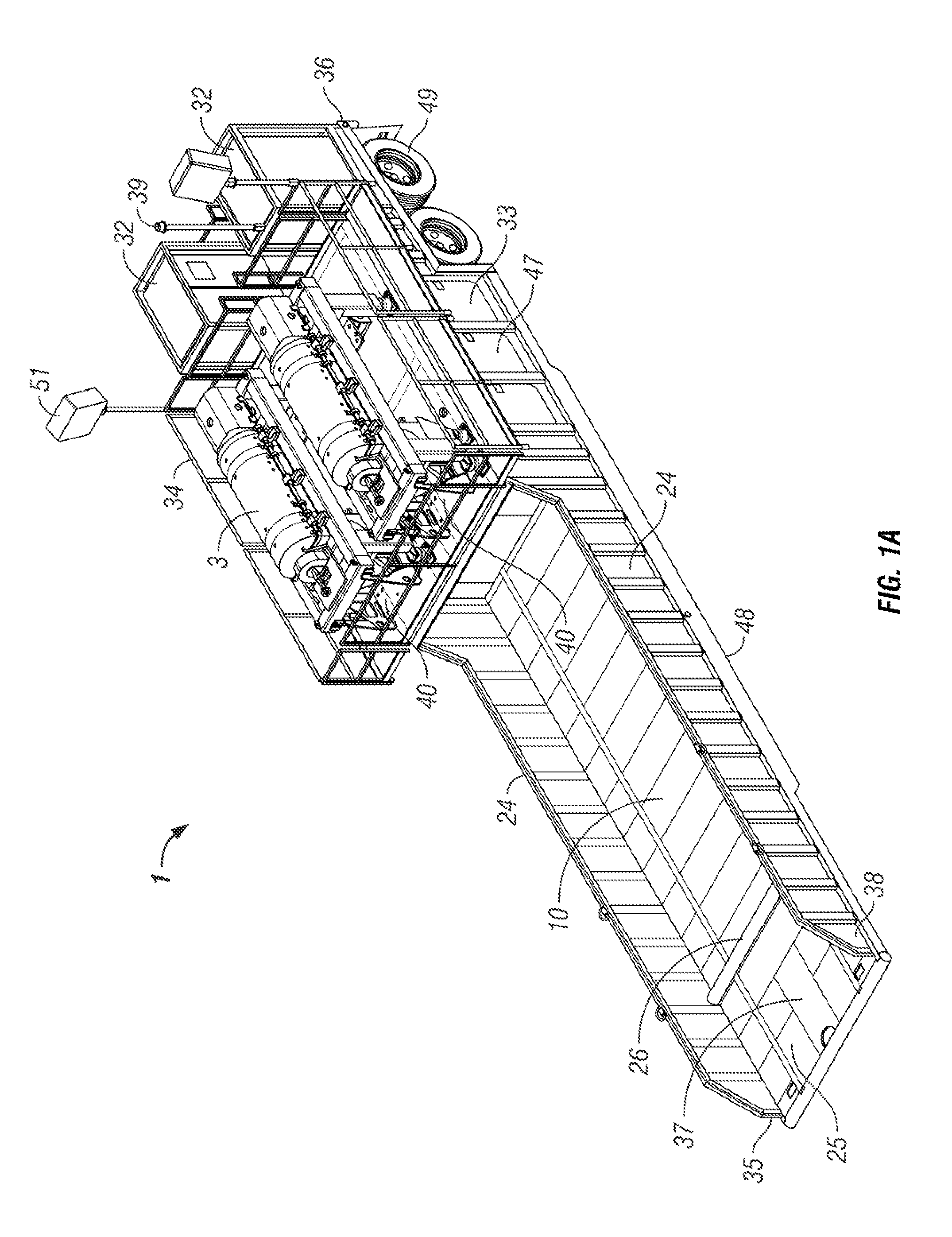
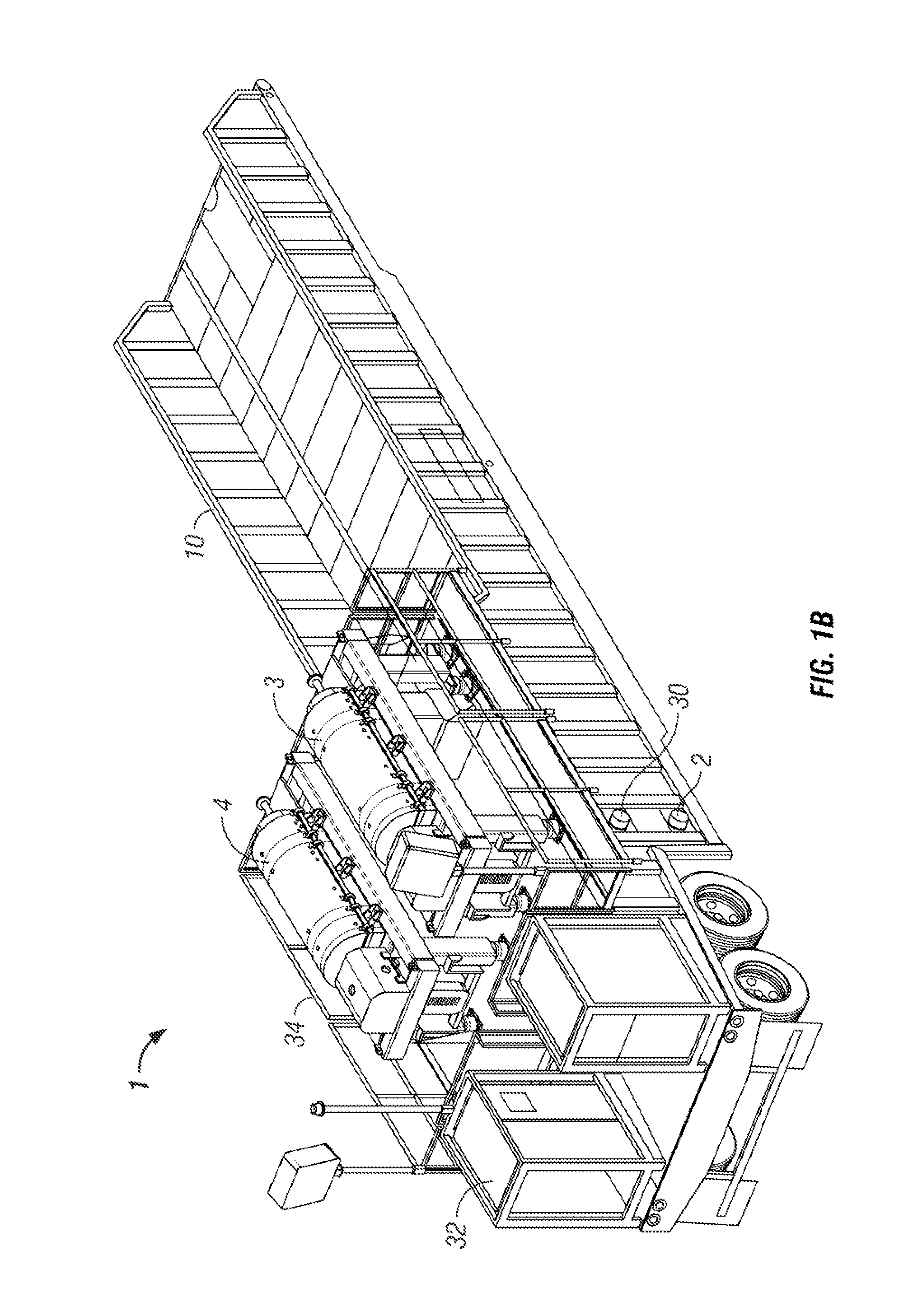
[0018]In one aspect, the embodiments disclosed herein relate to a mobile drilling waste management system comprising a mobile trailer. In another aspect, the trailer may include the centrifuges, pumps, tanks, piping assemblies, controllers, and other equipment necessary to reclaim drilling fluids contaminated with solids that cannot be removed by conventional “shale shakers” on the drilling rig.

[0019]Advantageously, by including the components onto a single trailer as described in the various embodiments, the solids-contaminated drilling fluid may be treated by positioning the trailer at the rig site and connecting the source of the contaminated drilling fluid to the trailer inlet. The mobile drilling waste management system of this invention thereby eliminates or reduces the need for multiple delivery loads, use of a crane to place the equipment, and complicated assembly of the system components. Thus, the mobile drilling waste management system of this invention may reduce the cos...


PUM

PropertyMeasurementUnit
liquid levelaaaaaaaaaa
liquid barrieraaaaaaaaaa
inlet flow rateaaaaaaaaaa

Abstract

A mobile drilling waste management system including a trailer having at least one centrifuge and a solids catch tank receiving solids separated from drilling fluid by one or more of the centrifuges. And a method of reclaiming drilling fluid including pumping drilling fluid contaminated with solids onto a trailer, separating the contaminant solids from the drilling fluid with at least one centrifuge located on the trailer, directing the contaminant solids to a solids catch tank located on the trailer, and pumping the drilling fluid off of the trailer.

Description

BACKGROUND OF INVENTION[0001]In the process of drilling wells, wellbore fluids or drilling muds are pumped downhole from the well drilling platform. Often these drilling fluids lubricate the drill bit and carry away cuttings generated as the drill bit digs. The cuttings and other solids are carried in a return flow stream with the fluids up to the well drilling platform at the surface. The solids are typically small pieces of shale or rock. Once the drilling fluids and solids reach the platform, a “shale shaker” located on the platform is typically used to remove the solids from the drilling fluids so that the fluids may be reused.[0002]But it is not always possible to separate all the solids from the drilling fluids with a shale shaker. Many times the solids are simply too small to be separated with a shaker. Generally, the shale shakers are only able to separate 60-70% of contaminant solids from drilling fluids. Additionally, drilling fluids are frequently formulated to contain fi...

Claims


Application Information

Patent Timeline
Patent Type & Authority Patents(United States)
IPC IPC(8): E21B21/06
CPCE21B21/065B01D21/262B01D2221/04
Inventor JACKSON, DENNISGILLIS, FREDRICKWHITE, JASON
Owner MI
Why Eureka
Try Eureka