RFID circuit element cartridge, roll for producing electromagnetic radiation reaction element label, and tag-label producing device

a technology of electromagnetic radiation reaction element and cartridge, which is applied in the direction of recording equipment, printing mechanisms, instruments, etc., can solve the problems of uneven configuration of the portion of the print-receiving tape where the electromagnetic radiation reaction element is provided, difficult to see, and inability to print in a satisfactory manner. , to achieve the effect of improving the soundness of the tag label product and improving the soundness and reliability of the tag label

Active Publication Date: 2013-09-10
BROTHER KOGYO KK
View PDF37 Cites 73 Cited by
  • Summary
  • Abstract
  • Description
  • Claims
  • Application Information

AI Technical Summary

Benefits of technology

[0016]A first object of the present invention is to provide a RFID circuit element cartridge, a roll for producing an electromagnetic radiation reaction element label, and a tag-label producing device, which can improve the soundness of the tag label product.
[0017]A second object of the present invention is to provide a roll for producing an electromagnetic radiation reaction element label, a RFID circuit element cartridge, and a tag-label producing device, which allow printing to be performed in a satisfactory manner even with respect to a tape member in which electromagnetic radiation reaction elements such as RFID circuit elements are arranged.
[0018]A third object of the present invention is to provide a RFID circuit element cartridge which can prevent a force acting to strip off the IC circuit part from the antenna from being generated to thereby improve the soundness and reliability of the tag label, and a tag-label producing device using the RFID circuit element cartridge.

Problems solved by technology

However, the above-mentioned related art techniques involve the following problems.
In this case, when the construction described in Patent Document 1 mentioned above is applied to the production of a tag label, the portion of the print-receiving tape where the electromagnetic radiation reaction element is provided becomes uneven in configuration.
As a result, printing may no longer be performed in a satisfactory manner or the resulting print may become hard to see, making it difficult to ensure the soundness of the tag label product.
Here, usually, the IC circuit part having a relatively small size exhibits a rigidity greater than that of the antenna having a relatively large size; in the case where, for example, the antenna is located on the radially inner peripheral side and the IC circuit part is located on the radially outer peripheral side at the time of the above-mentioned deflection, although it is relatively easy for the antenna to follow and deflect along the shape of the roller or the like, it is generally rather difficult for the IC circuit part to follow and deflect along the shape of the roller or the like.
As a result, a force acting to strip off the IC circuit part from the antenna is generated at the time of the above-mentioned deflection, which reduces the soundness and reliability of the completed tag label product.

Method used


Image

  • RFID circuit element cartridge, roll for producing electromagnetic radiation reaction element label, and tag-label producing device
  • RFID circuit element cartridge, roll for producing electromagnetic radiation reaction element label, and tag-label producing device
  • RFID circuit element cartridge, roll for producing electromagnetic radiation reaction element label, and tag-label producing device

Examples


first embodiment

[0049]the present invention will be described with reference to FIGS. 1 to 17.

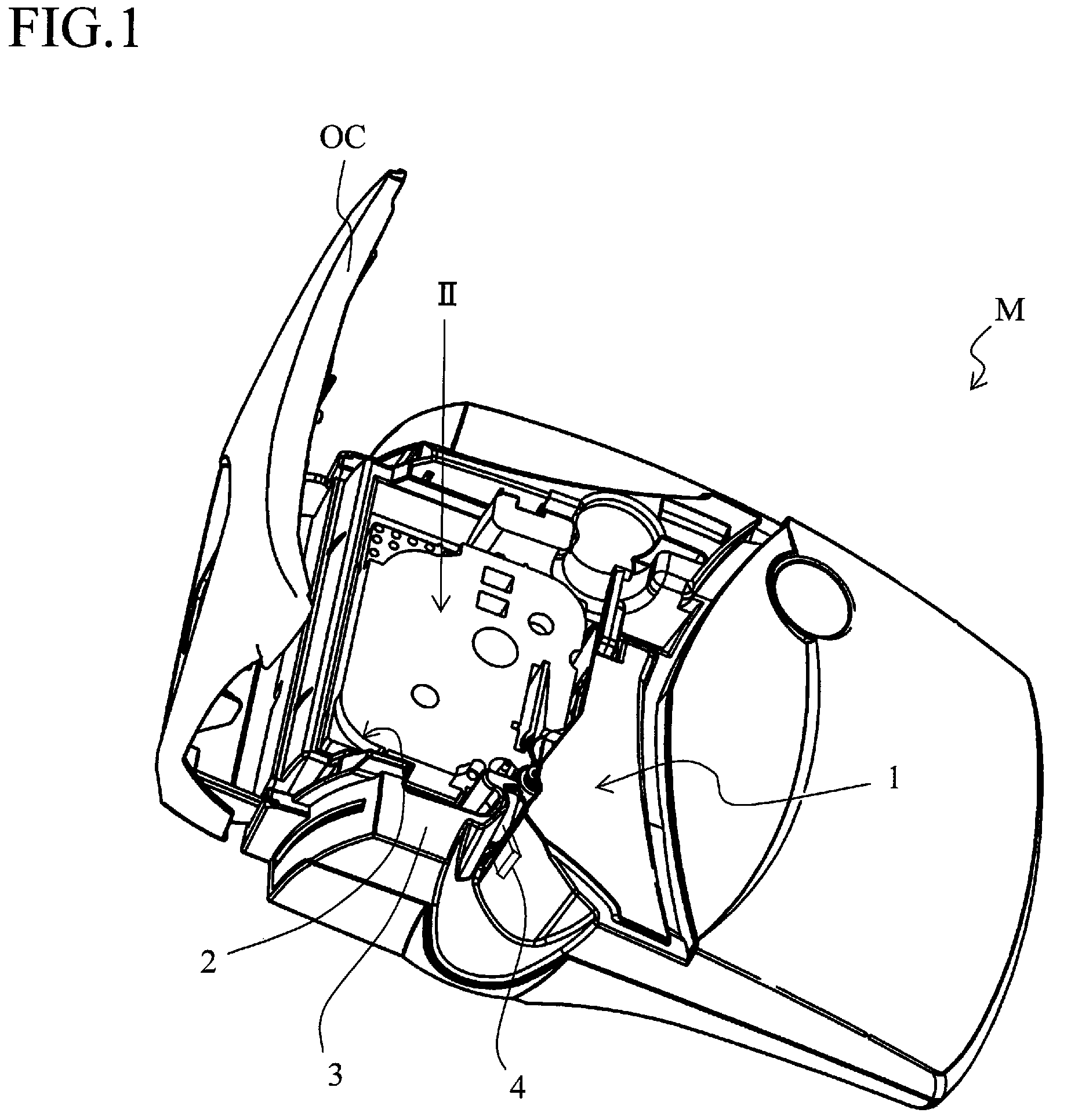
[0050]FIG. 1 is a perspective view showing the general overall structure of a tag-label producing device (in the state where a cartridge 100 that will be described later is mounted and an open / close cover OC is opened) according to this embodiment.

[0051]In FIG. 1, a tag-label producing device (tape producing device) M includes a main body 1, a cartridge holder part 2 for accommodating the cartridge (RFID circuit element cartridge) 100 detachably mounted to the main body 1, a housing 3 forming the outer shell of the main body 1, an antenna 4 for performing exchange of signals through wireless communication using a radio frequency in the UHF band or the like, and the open / close cover OC pivotably connected to the main body 1 so as to cover the cartridge holder part 2 when closed.

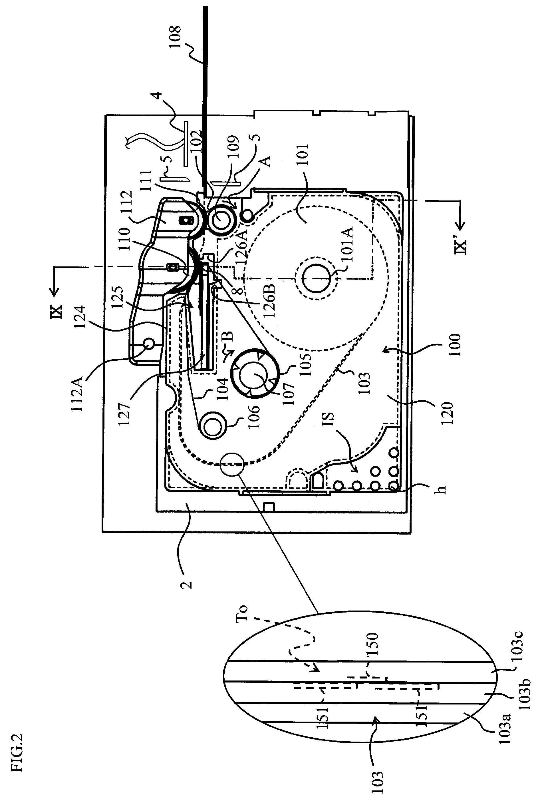
[0052]FIG. 2 is a (partially see-through) top view showing, together with the cartridge 100, the portion of the main body 1 in the ...


PUM

PropertyMeasurementUnit
widthaaaaaaaaaa
sizeaaaaaaaaaa
areaaaaaaaaaaa

Abstract

A cartridge includes a tag tape roll around which a tag tape is wound, said tag tape having a plurality of RFID circuit elements aligned in a safety area, which is located at an end on one side in the width direction of said tag tape, and including a print area on the other side in the width direction with respect to said RFID circuit elements. A tag label producing device performs predetermined printing on said print area by a print head while paying out said tag tape from said tag tape roll, and produces a tag label by using said tag tape on which printing has been performed.

Description

CROSS-REFERENCE TO RELATED APPLICATION[0001]This is a CIP application PCT / JP2005 / 5977, filed Mar. 29, 2005, which was not published under PCT article 21(2) in English.BACKGROUND OF THE INVENTION[0002]1. Field of the Invention[0003]The present invention relates to a roll for producing an electromagnetic radiation reaction element label for producing an electromagnetic radiation reaction element label in a continuous tape-like form, a tag-label producing device as the electromagnetic radiation reaction element label producing device, and a RFID circuit element cartridge using the tag-label producing device.[0004]2. Description of the Related Art[0005]Conventionally, there has already been proposed a tape printing device (label producing device) which has a tape serving as a print-receiving material accommodated in a roll within a cartridge (cassette) and is adapted to print desired characters onto the tape as it is paid out from the roll and discharge the tape in the form of a label (...

Claims


Application Information

Patent Timeline
Patent Type & Authority Patents(United States)
IPC IPC(8): B41J3/36B41J25/304B41J15/04B41J3/407G06K19/07G06K19/077
CPCB41J3/4075B41J15/044G06K17/0025B41J25/304
Inventor TANAKA, MITSUGI
Owner BROTHER KOGYO KK
Why Eureka
Try Eureka