Spinning tower rack

a tower rack and spinning technology, applied in the field of spinning tower racks, can solve the problems of occupying a lot of foot space in the retail store, not much flexibility in the manner in which cards can be displayed, and customers having to move down the length of the display case, etc., to achieve the effect of simple assembly, extreme durability, and elegant design

Active Publication Date: 2013-09-17
UNIVERSAL PRESENTATION CONCEPTS
View PDF53 Cites 12 Cited by
  • Summary
  • Abstract
  • Description
  • Claims
  • Application Information

AI Technical Summary

Benefits of technology

[0009]The display described is an innovative design which answers to the wholesale / retail / consumer needs to best promote the sale of the product displayed in a minimal amount of square footage. Its creation features elegance of design, simplicity of assembly, extreme durability and most importantly an uninterrupted view or encumbrance of the product displayed.

Problems solved by technology

Therefore, there is not much flexibility in the manner the cards can be displayed.
A disadvantage of such displays is that they take up quite a bit of foot space in the retail stores.
Another disadvantage is that the customer must typically move down the length of the display case in order to view all the cards.

Method used


Image

  • Spinning tower rack
  • Spinning tower rack
  • Spinning tower rack

Examples


Embodiment Construction

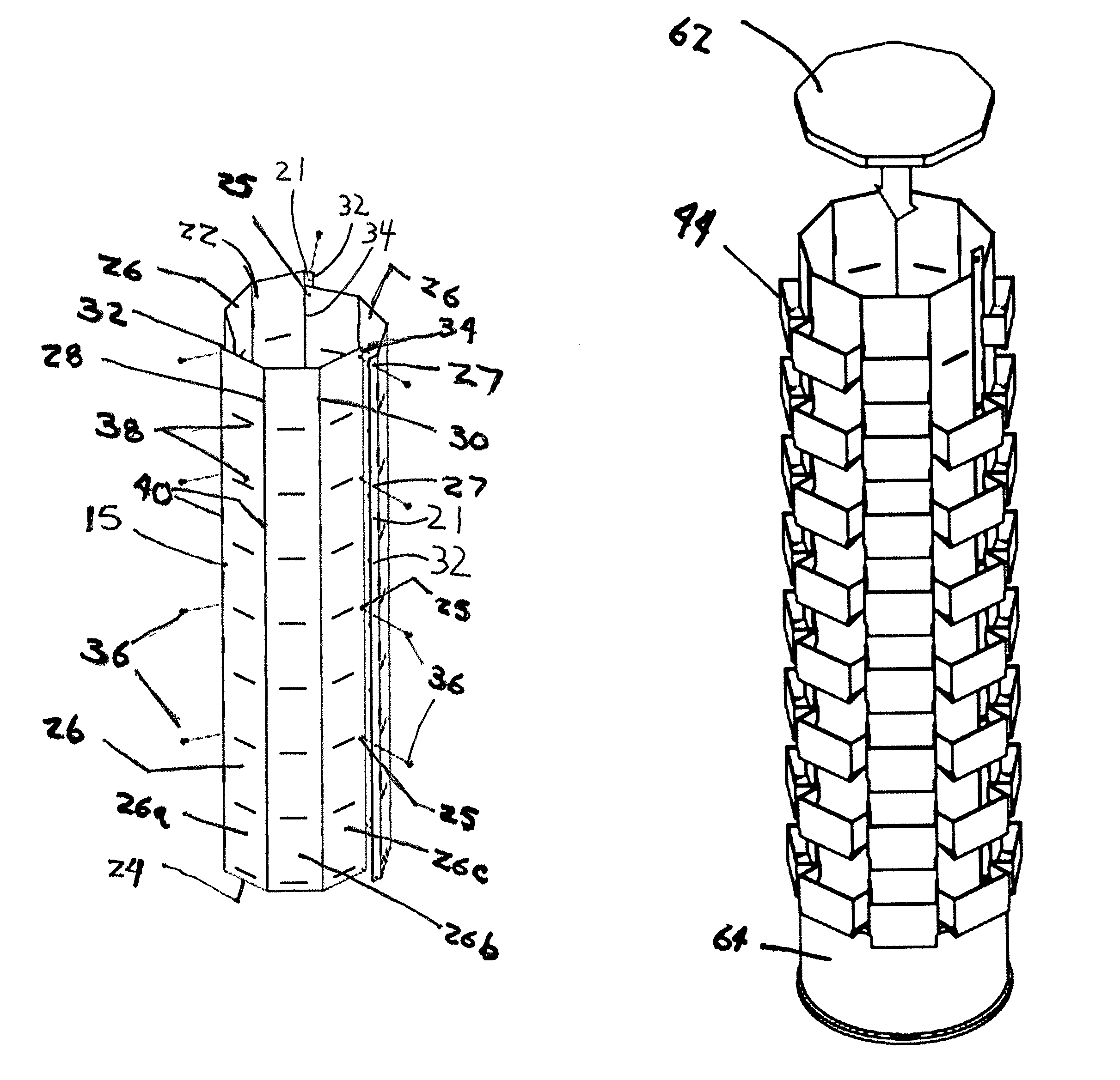
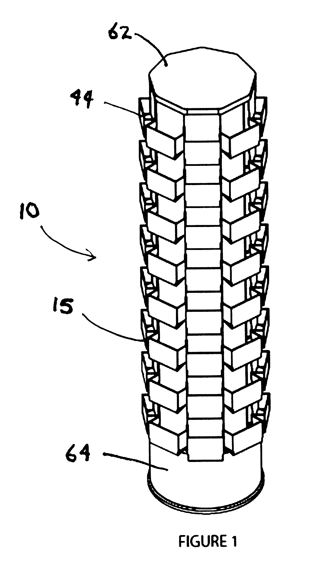
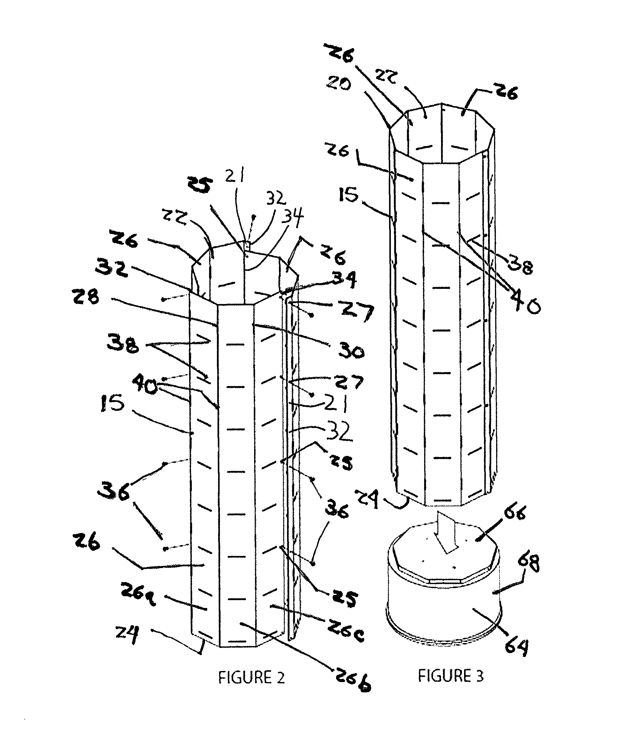
[0024]Referring now to FIGS. 1-6, there is illustrated a single spinning tower rack 10 of the current invention, which most generally includes a tower assembly 15, a cap or top portion 62 and a bottom portion or base 64. The tower assembly 15 includes a tower prism 20. The tower prism 20 takes the geometric form of a multi-sided prism tube with open ends 22, 24. FIGS. 1-6 illustrate the tower prism 20 as a nonagon (9-sided) prism. However, the tower prism 20 may have any number of sides, including 3, 4, 5, etc., or even 0 sides in the case of a cylindrical tube form. As illustrated in FIG. 2, the tower prism 20 is comprised of three identical panel sections 26 that connect together in a daisy chain fashion to each other. Each panel section 26 is formed with three faceted side panels 26a, 26b, and 26cconnected at borders 28 and 30. The three faceted panels 26 combine to form the sides of the tower prism 20. The attachment of the three panels 26 is achieved by overlapping a flap 21 of...


PUM


Abstract

A tower rack for holding greeting cards and the like is described. The rack includes a tower assembly structure which includes at least one panel section consisting of one or more side panels. Each side panels is configured with horizontal and vertical slits for holding merchandise trays. A base is configured to fit snugly to the bottom of the tower assembly structure.

Description

REFERENCE TO RELATED APPLICATION[0001]The application claims priority to U.S. Provisional Application entitled “Spinning Tower Rack,” Ser. No. 61 / 243,021, filed Sep. 16, 2009, which is incorporated herein by reference in its entirety.FIELD OF THE INVENTION[0002]The present invention is directed to a spinning tower rack used to exhibit cards or other items on a rotating display.DESCRIPTION OF THE PRIOR ART[0003]Greeting card displays in retail stores take many forms and are generally designed to provide the customer with a wide variety of cards and other merchandise preferably in a compact arrangement and in a manner to minimize the space requirements for the display. Most displays are typically presented as successive rows of card shelves along the wall of a store or in back-to-back fashion. The displays include a front panel, rear panel, two side panels and elevating rows of “card slots” such the customer will be able to view as many cards as possible. In such cases, the spacing of...

Claims


Application Information

Patent Timeline
Patent Type & Authority Patents(United States)
IPC IPC(8): A47F5/02A47F3/14A47J47/00
CPCA47F5/02A47F5/04A47F7/146
Inventor LEVINE, DANIEL E.STANCER, III, FRED C.ATWOOD, ALAN C.
Owner UNIVERSAL PRESENTATION CONCEPTS
Why Eureka
Try Eureka