Method and system for providing a magnetic transducer having improved shield-to-shield spacing

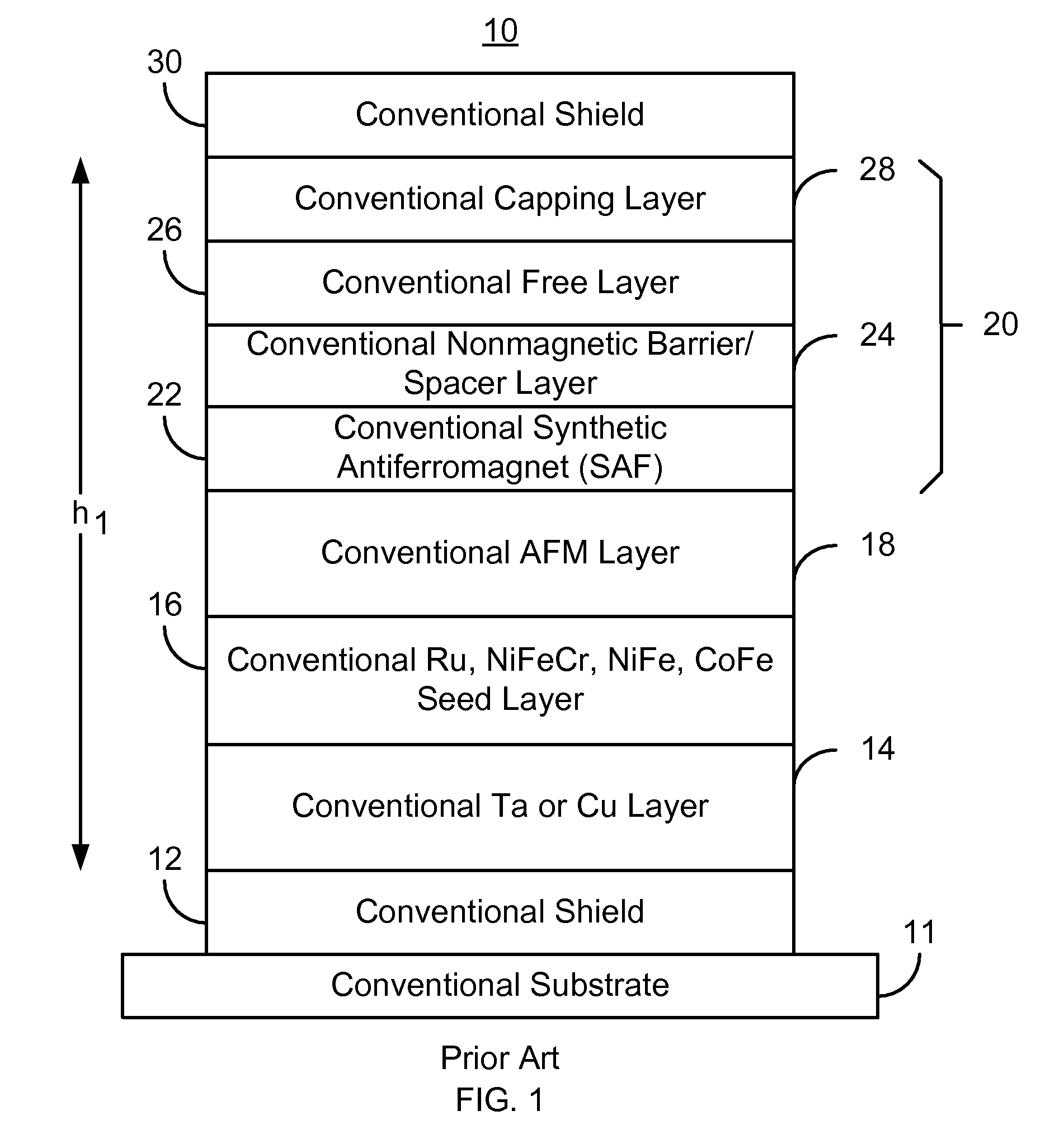
a technology of shield-to-shield spacing and magnetic transducer, which is applied in the direction of magnetic bodies, instruments, and heads with metal sheet cores, etc., can solve the problems of adversely affecting the performance of the conventional transducer b>10/b>, affecting the performance of the conventional transducer, and arising in the field of higher density magnetic recording applications

Inactive Publication Date: 2013-09-17
WESTERN DIGITAL TECH INC
View PDF14 Cites 152 Cited by
  • Summary
  • Abstract
  • Description
  • Claims
  • Application Information

AI Technical Summary

Problems solved by technology

Although the conventional transducer 10 and conventional sensor 20 may function, issues may arise in higher density magnetic recording applications.
However, reduction of the thickness of various layers, such as the conventional AFM layer 18 or conventional seed layers 14 and 16 adversely affects performance of these layers.
Consequently performance of the conventional transducer 10 is adversely affected.
Consequently, performance of the conventional magnetic transducer 10 may again be adversely impacted.

Method used


Image

  • Method and system for providing a magnetic transducer having improved shield-to-shield spacing
  • Method and system for providing a magnetic transducer having improved shield-to-shield spacing
  • Method and system for providing a magnetic transducer having improved shield-to-shield spacing

Examples


Embodiment Construction

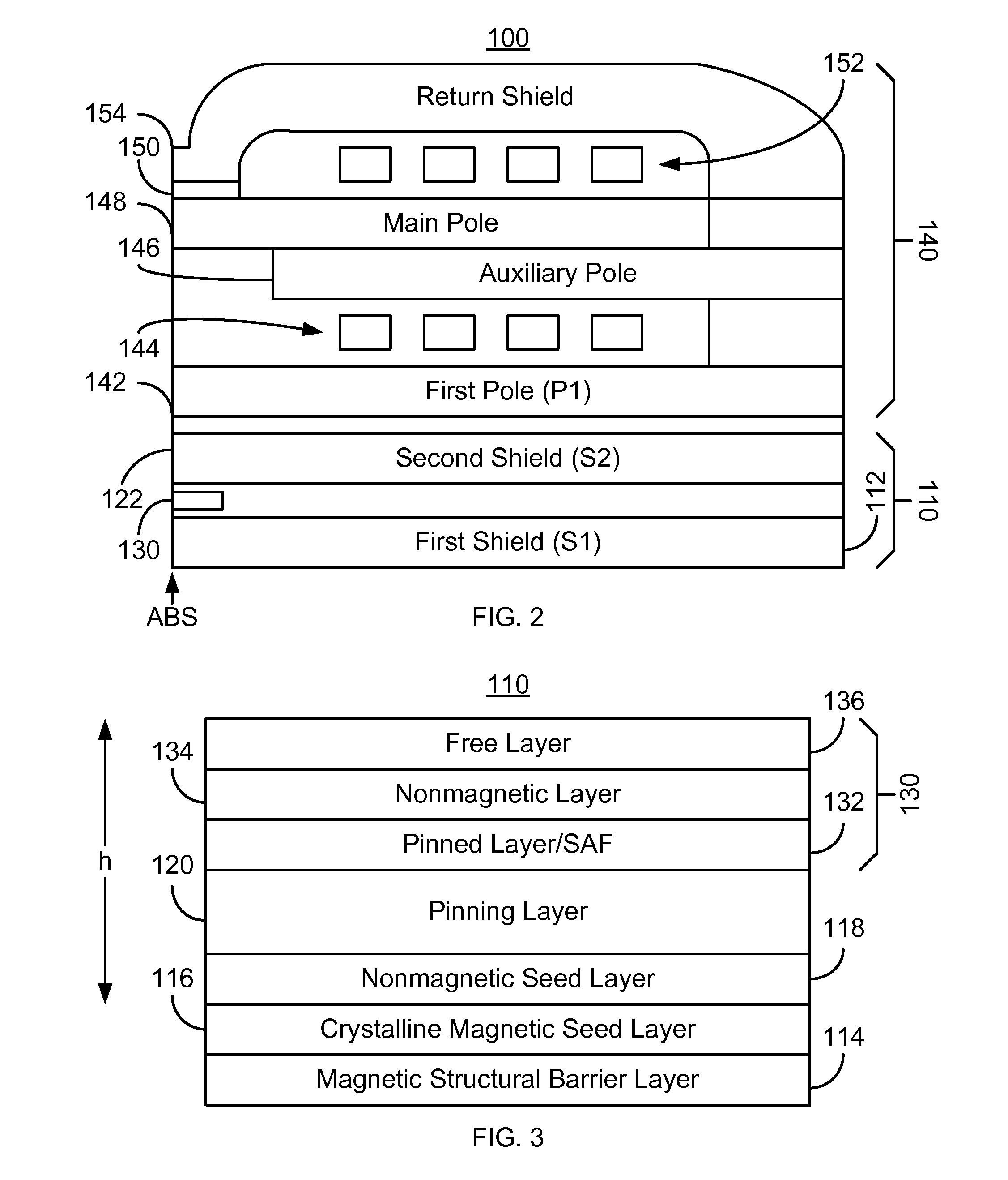
[0011]FIG. 2 depicts a magnetic head 100. The magnetic head includes a magnetic read transducer 110 and write transducer 140. FIG. 3 depicts an exemplary embodiment of a portion of transducer 110 including an exemplary embodiment of seed layers. FIG. 3 may be considered a portion of the ABS view of the transducer 110. Referring to FIGS. 2-3, in another embodiment, the head 100 might include only the read transducer 110. The head 100 may reside on a slider (not shown) of a disk drive (not shown). The head 100 is also described in the context of particular layers. However, in some embodiments, such layers may include sub-layer(s). For clarity, FIGS. 2-3 are not drawn to scale.

[0012]The write transducer 140 includes a first pole 142, auxiliary pole 146, main pole 148, write gap 150, coils 144 and 152, and return shield 154. However, in another embodiment, the write transducer 140 other and / or different components. In addition, one or more portions of the write transducer 140 might be o...


PUM

PropertyMeasurementUnit
thicknessaaaaaaaaaa
thicknessaaaaaaaaaa
thicknessaaaaaaaaaa

Abstract

A method and system for providing a magnetic transducer is described. The method and system include providing a magnetic structural barrier layer and a crystalline magnetic layer on the magnetic structural barrier layer. The magnetic structural barrier layer may reside on a shield. The method and system also include providing a nonmagnetic layer on the crystalline magnetic layer. A pinning layer is provided on the nonmagnetic layer. Similarly, a pinned layer is provided on the pinning layer. The pinning layer is magnetically coupled with the pinned layer. The method and system also include providing a free layer and a nonmagnetic spacer layer between the pinned layer and the free layer.

Description

BACKGROUND[0001]FIG. 1 depicts a portion of a conventional magnetic transducer 10, such as a conventional read transducer or other device. The conventional transducer 10 resides on a conventional substrate 11, such as an AlTec substrate. The conventional transducer 10 includes a conventional bottom shield 12, conventional seed layers 14 and 16, conventional antiferromagnetic (AFM) layer 18, conventional sensor 20, and conventional top shield 30. The conventional bottom seed layer 14 typically includes Ta or Cu and adjoins, or shares an interface with, the conventional shield 12. The thickness of the Ta layer 14 is typically twenty through fifty Angstroms. The conventional seed layer 16 typically includes Ru, NiFeCr, NiFe, or CoFe and adjoins the conventional nonmagnetic seed layer 14. Thus, the conventional seed layers 14 and 16 may be viewed as forming a bi-layer seed layer including, for example, Ta / Ru, Ta / NiFe, Ta / NiFeCr, or Ta / CoFe layers. The conventional shields 12 and 30 typi...

Claims


Application Information

Patent Timeline
Patent Type & Authority Patents(United States)
IPC IPC(8): G11B5/127
CPCG11B5/3906H01F10/30G01R33/093H01L43/08G11B5/3929Y10T428/1193H01F10/3272H10N50/10G11B5/147G11B5/3116
Inventor PARK, CHANDOLENG, QUNWENOH, SANGMUNPAKALA, MAHENDRA
Owner WESTERN DIGITAL TECH INC
Why Eureka
Try Eureka