
Wake generating solid elements for joule heating or infrared heating

a solid element and wake generation technology, applied in immersion heating arrangements, lighting and heating apparatus, furnaces, etc., can solve the problems of deficient current resistance heating wires, high production costs, and many other problems, and achieve the effect of reducing drag and pressure drop

Active Publication Date: 2013-09-24
MOSKAL DANIEL
View PDF28 Cites 11 Cited by
  • Summary
  • Abstract
  • Description
  • Claims
  • Application Information

AI Technical Summary

Benefits of technology

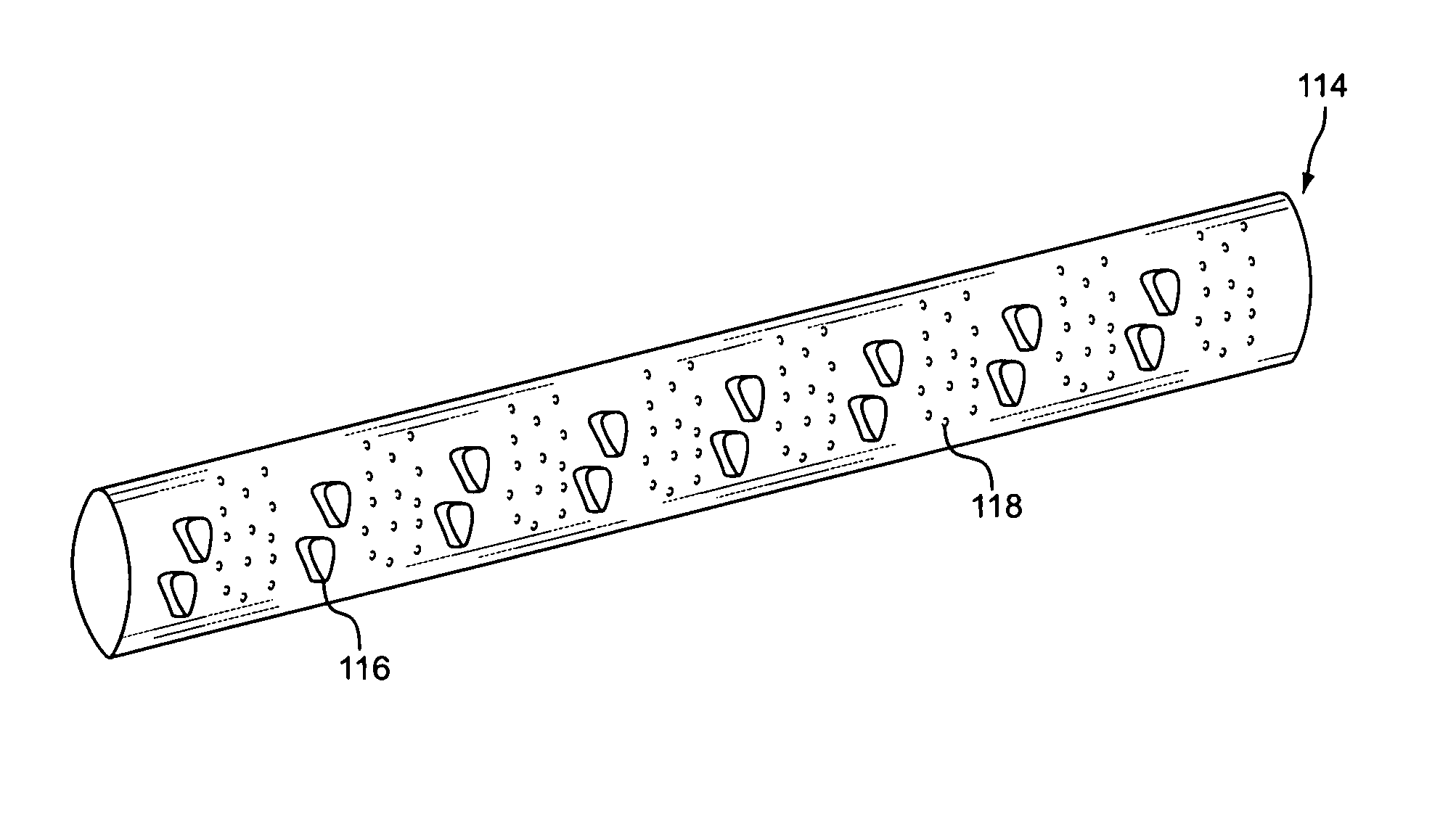
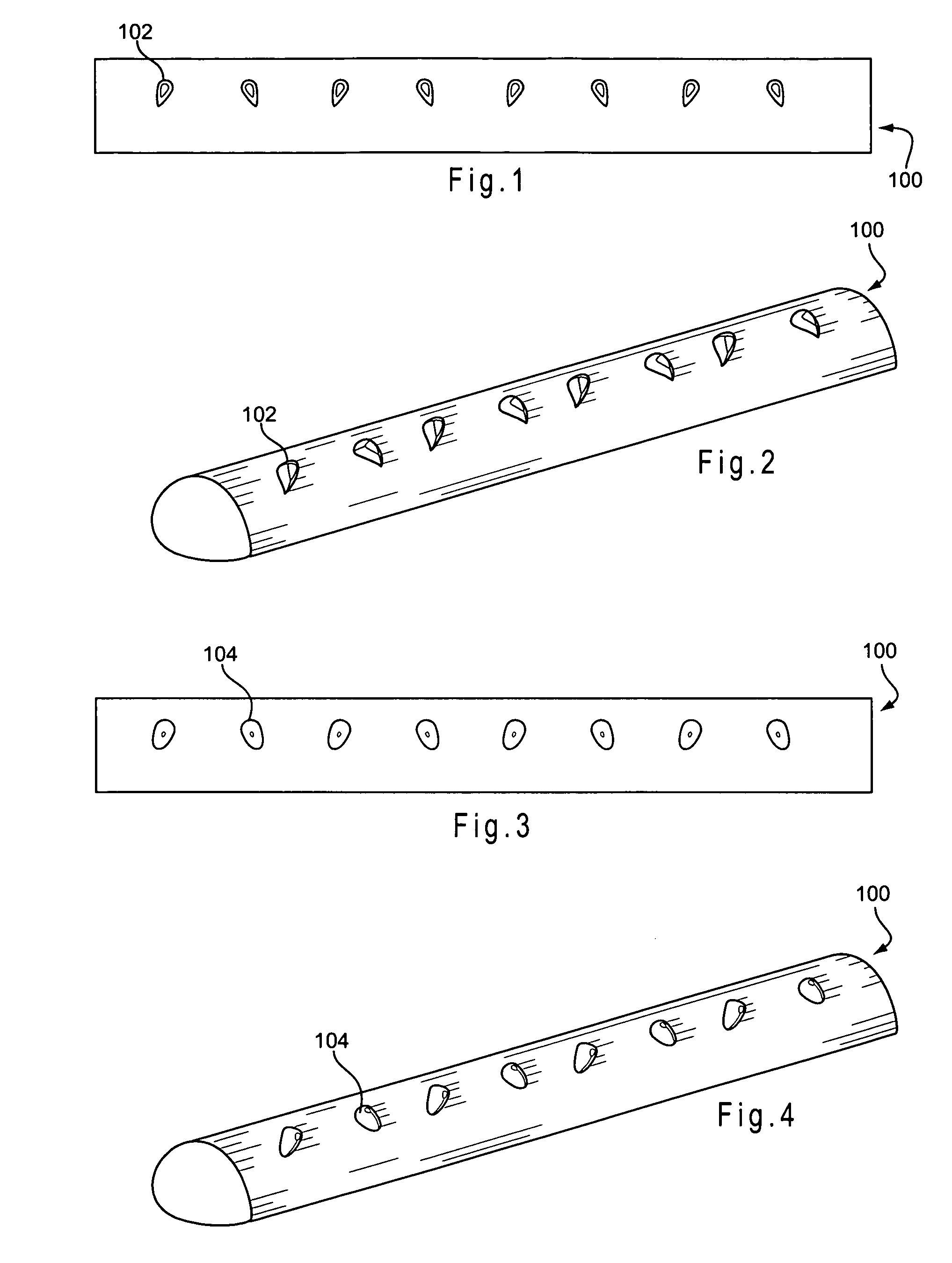
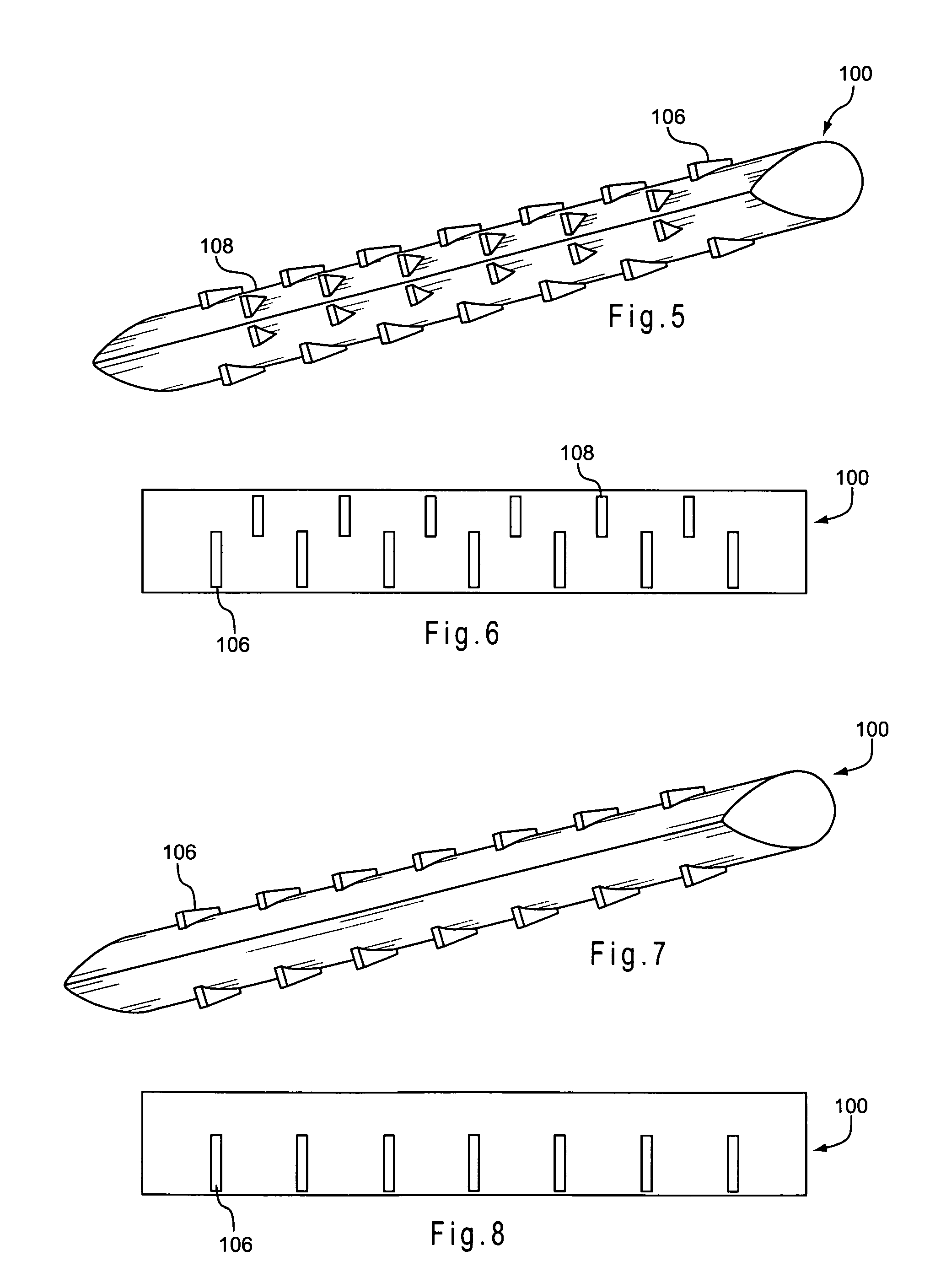
[0007]According to one aspect of the present invention, a solid heat transfer element is provided for generating heat from an electric current passing through its electrically resistant material and transferring the heat to a fluid flow in communication with the solid heat transfer element. The solid heat transfer element includes an elongate member composed of electrically resistive, heat generating material placed transversely to the fluid flow with an aerodynamic profile, symmetrical in respect to the fluid flow, configured to provide reduced drag and pressure drop when compared to less aerodynamic profile shapes using the same volume of material. For example, a tear drop shaped profile is generally more aerodynamic than a circular profile. The elongate member has a cylindrical surface including a surface area in contact with the fluid flow and male protrusions extending from the cylindrical surface into the fluid flow, the male protrusions configured to provide additional surface area in contact with the fluid flow and to generate vortices to mix heated fluid layers.
[0017]In another aspect of the present invention, a solid heat transfer element is provided for absorbing energy from a source of electromagnetic radiation and transferring the energy as heat to a fluid flow in communication with the solid heat transfer element. The solid heat transfer element is an elongate member adapted to absorb electromagnetic radiation, the elongate member oriented transversely to the fluid flow and exposed to the source of electromagnetic radiation. The elongate member has an aerodynamic profile that is symmetrical with respect to the fluid flow, to provide relatively low drag and pressure drop, as discussed above. A cylindrical outer surface of the elongate member has a surface area in contact with the fluid flow and male protrusions extending from the cylindrical surface into the fluid flow, the male protrusions configured to provide additional surface area in contact with the fluid flow and to generate vortices to mix heated fluid layers.

Problems solved by technology

However, current resistance heating wires are deficient because they cause significant pressure drops and do not transfer heat effectively.
However, they are deficient in many ways.
For instance, their complex design makes them expensive to produce.
The fins typically extend well above the normal boundary layer and create significant turbulence, and so they do not control pressure drop well in relation to the benefit of increased heat transfer.
In addition, the multiple parts necessitate that finned strip heating elements be significantly larger in profile than heating elements typically are, which may limit the applications for which they can be utilized.
This is not effective when heating gas directly.
One known design is a flat plate which transfers the heat via natural convection, providing poor heat transfer.
However, round elements are not ideal for heat transfer and cause large pressure drops.

Method used


Image

  • Wake generating solid elements for joule heating or infrared heating
  • Wake generating solid elements for joule heating or infrared heating
  • Wake generating solid elements for joule heating or infrared heating

Examples


Embodiment Construction

[0135]This invention is a substantially new way to look at solid heat transfer elements placed in a fluid stream for the purpose of efficient surface heat transfer to the fluid stream via forced or natural convection. The solid heat transfer elements of the present invention are in contact with only one fluid flow. The fluid is moved by means of fans, propellers, gravity, suction or other mechanical means of moving air or gases, or by natural convection. The solid heat transfer element's source of heat comes from electricity, not mechanical energy, the solid element being heated by resistance to electric flow passing through it, by absorbing infrared radiation from a source external to the solid heat transfer element, typically an infrared emitting lamp, or by absorbing radio wave electromagnetic radiation, typically from a magnetron. The present invention utilizes vortex generators to increase heat transfer. Specifically, the use of vortex generators, also known as turbulators, inc...


PUM

PropertyMeasurementUnit
angleaaaaaaaaaa
angleaaaaaaaaaa
angle of attackaaaaaaaaaa

Abstract

An improved solid heat transfer element composed of an elongate member having a generally cylindrical surface with male vortex generating protrusions is provided. The vortex generating protrusions, which may be referred to as “turbulators,” provide improved heat transfer by convection to a flow of air transverse to the elongate members without substantially increasing the pressure drop in the flow of air passing over the members. Advantageously, a plurality of the heat transfer elements, or of straight portions of a single serpentine heat transfer element, may be arranged in an aligned or staggered array of elements or straight portions. Many advantageous profile shapes of the element and vortex generators are provided, including aerodynamic profile shapes that are symmetrical with respect to a fluid flow to provide low drag and pressure drop. Heat in the element may be generated by means of electrical resistance or absorption of radiation.

Description

FIELD OF INVENTION[0001]This invention relates to improved solid heating elements providing good heat transfer and low pressure drop.BACKGROUND OF THE INVENTION[0002]“Solid heat transfer element” is a term used to describe heat transfer bodies that are in contact with one fluid flow at a time and are solid in the center. For example, one known type of solid heat transfer element is resistance heating wire where the heat is created by electricity passing through electrically resistive material. Another type is a solid element made of material that absorbs infrared heat, the infrared radiation typically being created by infrared lamps.[0003]Resistance heating wire was one of the first applications of electricity, and many designs exist. However, current resistance heating wires are deficient because they cause significant pressure drops and do not transfer heat effectively.[0004]Finned strip heating elements are a well known alternative form of electrical resistance heating element. T...

Claims


Application Information

Patent Timeline
Patent Type & Authority Patents(United States)
IPC IPC(8): H05B3/06F28D15/00
CPCB21D53/02H05B6/108B21D31/02Y10T29/4935F28F2215/00
Inventor MOSKAL, DANIELMARONGIU, MAURICE J.
Owner MOSKAL DANIEL
Learn More