Supercharge Your Innovation With Domain-Expert AI Agents!

Inspection circuit, electro-optic device, and electronic apparatus

a technology of inspection circuit and electro-optic device, which is applied in the direction of static indicating device, individual semiconductor device testing, instruments, etc., can solve the problems of unstable clock signal for operating inspection circuit, energy waste, etc., and achieve the effect of reducing power consumption and reducing the malfunction of electro-optic devi

Active Publication Date: 2013-09-24
SEIKO EPSON CORP
View PDF31 Cites 2 Cited by
  • Summary
  • Abstract
  • Description
  • Claims
  • Application Information

AI Technical Summary

Benefits of technology

[0007]An advantage of some aspects of the invention is to provide an inspection circuit capable of reducing its power consumption and also reducing a malfunction of an electro-optic device, an electro-optic device including the inspection circuit, and an electronic apparatus.

Problems solved by technology

Disadvantageously, energy is wasted.
In addition, when the inspection circuit is supplied with a power supply voltage while not operating, a clock signal for operating the inspection circuit becomes unstable.
This may cause a malfunction of the electro-optic device.
More specifically, a display defect, such as crosstalk, may be generated.
It is therefore difficult to reliably reduce power consumed by the supply circuit.
Accordingly, if the line is charged with static electricity, the electro-optic device may malfunction due to the static electricity influenced through the inspection circuit.

Method used


Image

  • Inspection circuit, electro-optic device, and electronic apparatus
  • Inspection circuit, electro-optic device, and electronic apparatus
  • Inspection circuit, electro-optic device, and electronic apparatus

Examples


Embodiment Construction

[0040]An inspection circuit according to an embodiment of the invention, an electro-optic device according to another embodiment of the invention, and an electronic apparatus according to another embodiment of the invention will be described below with reference to FIGS. 1 to 8. In the following embodiments, a TFT active matrix driving liquid crystal display device will be described as an example of the electro-optic device according to the embodiment of the invention.

Liquid Crystal Display Device and Inspection Circuit

[0041]The liquid crystal display device and the inspection circuit mounted on the liquid crystal display device according to the embodiments will be described with reference to FIGS. 1 to 7. In the embodiments, the inspection circuit is mounted on the liquid crystal display device.

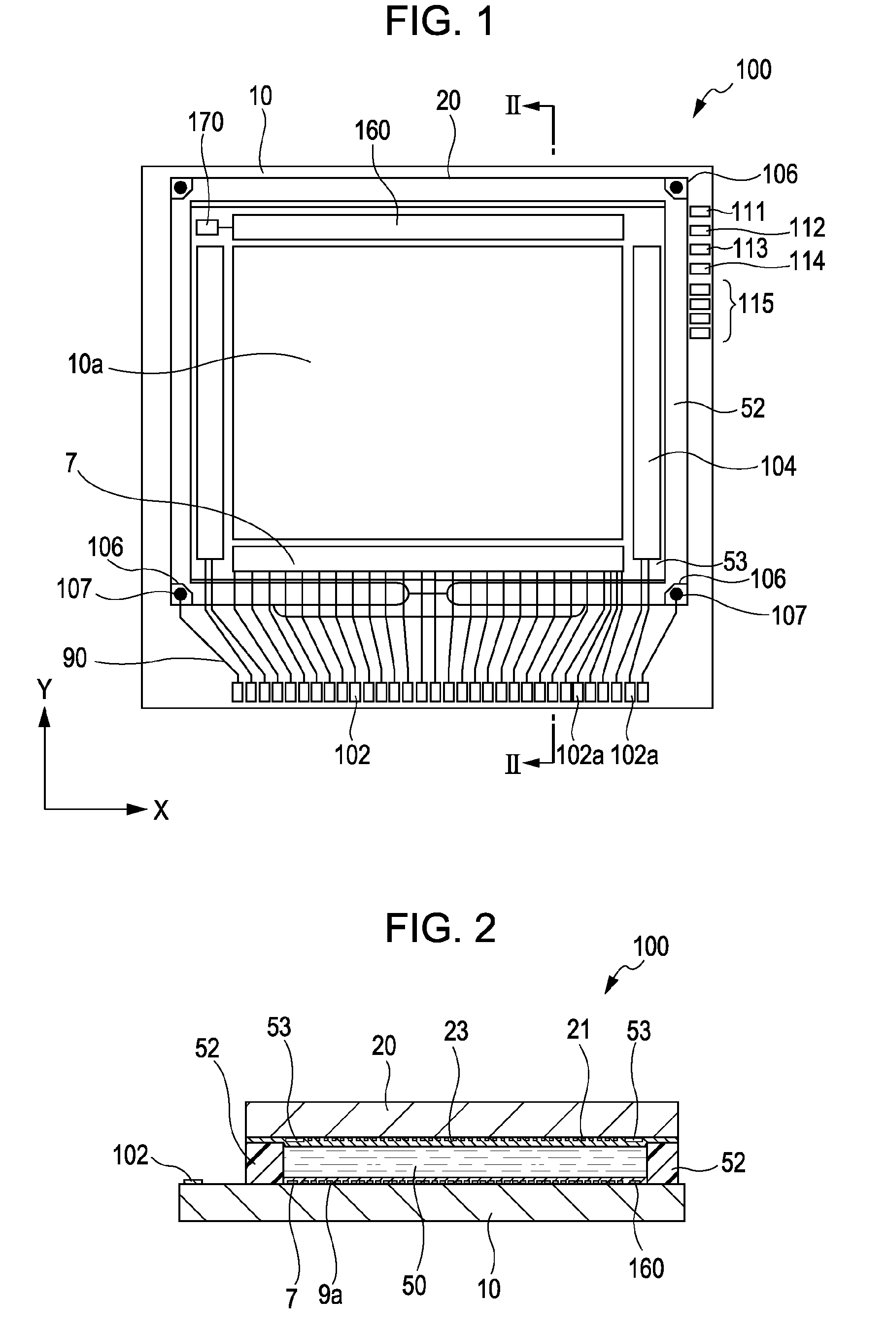
[0042]First, the entire structure of the liquid crystal display device, indicated at 100, according to the embodiment will be described with reference to FIGS. 1 and 2. FIG. 1 is a plan view...


PUM


Abstract

An inspection circuit for inspecting an electro-optic device that includes a data line, a scanning line, a pixel portion, a driving circuit, and a first terminal portion through which a first power supply voltage is supplied to the driving circuit. The inspection circuit includes an inspection line electrically connected to an inspection unit inspecting the pixel portion, a connection circuit electrically connecting the inspection line to the data line, and a supply circuit supplying a control signal for controlling conduction between the data line and the inspection line to the connection circuit. The supply circuit is driven using a second power supply voltage supplied through a second terminal portion.

Description

BACKGROUND[0001]1. Technical Field[0002]The present invention relates to a technical field of an inspection circuit for inspecting an electro-optic device, e.g., a liquid crystal display device, an electro-optic device, such as a liquid crystal display device, including the inspection circuit, and an electronic apparatus, such as a projector.[0003]2. Related Art[0004]In this type of electro-optic device, generally, inspection to determine the presence or absence of a defect is performed during manufacture in order to prevent the defect from seriously affecting post-processing. In particular, in an active matrix electro-optic device, since active elements, such as transistors, for switching pixels are arranged in an element substrate, it is important to determine the presence or absence of such a defect.[0005]Furthermore, in a driving circuit built-in electro-optic device, since part or the whole of the driving circuit is formed together with active elements for switching pixels in a...

Claims


Application Information

Patent Timeline
Patent Type & Authority Patents(United States)
IPC IPC(8): G01R31/26
CPCG09G3/006G02F2203/69G09G3/3648G09G2310/0297G09G3/36G09G3/20G02F1/133
Inventor ISHII, KENYA
Owner SEIKO EPSON CORP
Features
  • R&D
  • Intellectual Property
  • Life Sciences
  • Materials
  • Tech Scout
  • Unparalleled Data Quality
  • Higher Quality Content
  • 60% Fewer Hallucinations
Learn More