Apparatus for mounting a surveillance camera

a technology for surveillance cameras and accessories, applied in closed-circuit television systems, candle holders, lighting support devices, etc., can solve the problems of additional expense of back boxes and installation of camera wiring through back boxes, and achieve the effect of convenient and secure installation, easy and quick installation

Active Publication Date: 2013-10-01
PELCO INC
View PDF18 Cites 14 Cited by
  • Summary
  • Abstract
  • Description
  • Claims
  • Application Information

AI Technical Summary

Benefits of technology

[0009]The mounting assembly of the present invention allows a recessed surveillance camera or other recessed electric fixture to be easily and securely installed in a hole in a support surface, such as a suspended ceiling or hollow wall, without the additional expense and installation requirements of a back box. When installed on a surveillance camera or other electric fixture by tightening members, such as screws, the mounting assembly of the present invention enables a user to insert the mounting assembly into the hole by applying pressure to the tightening members which causes the flexible member of the mounting assembly to bend so that the mounting assembly is easily and quickly installed into through the hole in the mounting surface. When a user removes the pressure from the tightening members, the flexible member unbends thereby causing the spring clips to move outwardly away from the center of the housing so that the spring clips support the camera on the back side of the supporting surface. The flexible member prevents the spring clips from rotating when a user tightens the tightening members drawing the camera to the front side of the mounting surface and the surface-bearing section of the spring clips to the back side of the mounting surface.

Problems solved by technology

Although the mounting assembly disclosed in U.S. Pat. No. 5,931,432 was a significant improvement over the prior art in providing a method to attach a surveillance camera to a ceiling or wall, it requires the additional expense of a back box and the installation of the camera wiring through the back box.

Method used


Image

  • Apparatus for mounting a surveillance camera
  • Apparatus for mounting a surveillance camera
  • Apparatus for mounting a surveillance camera

Examples


Embodiment Construction

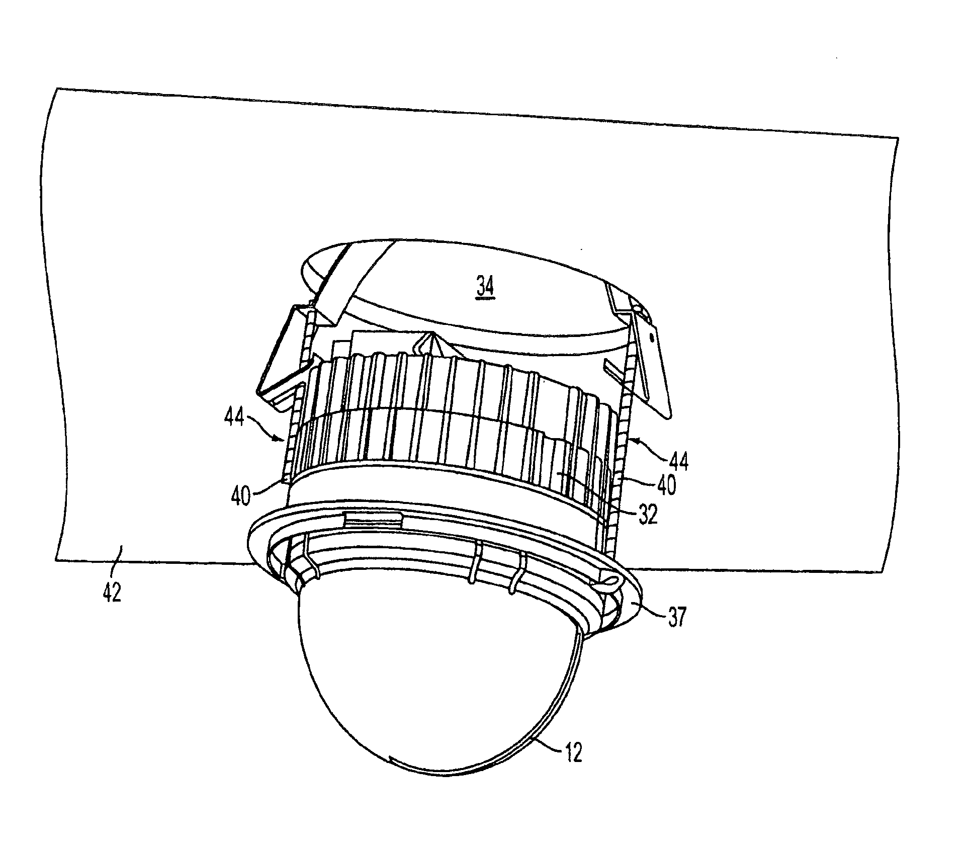
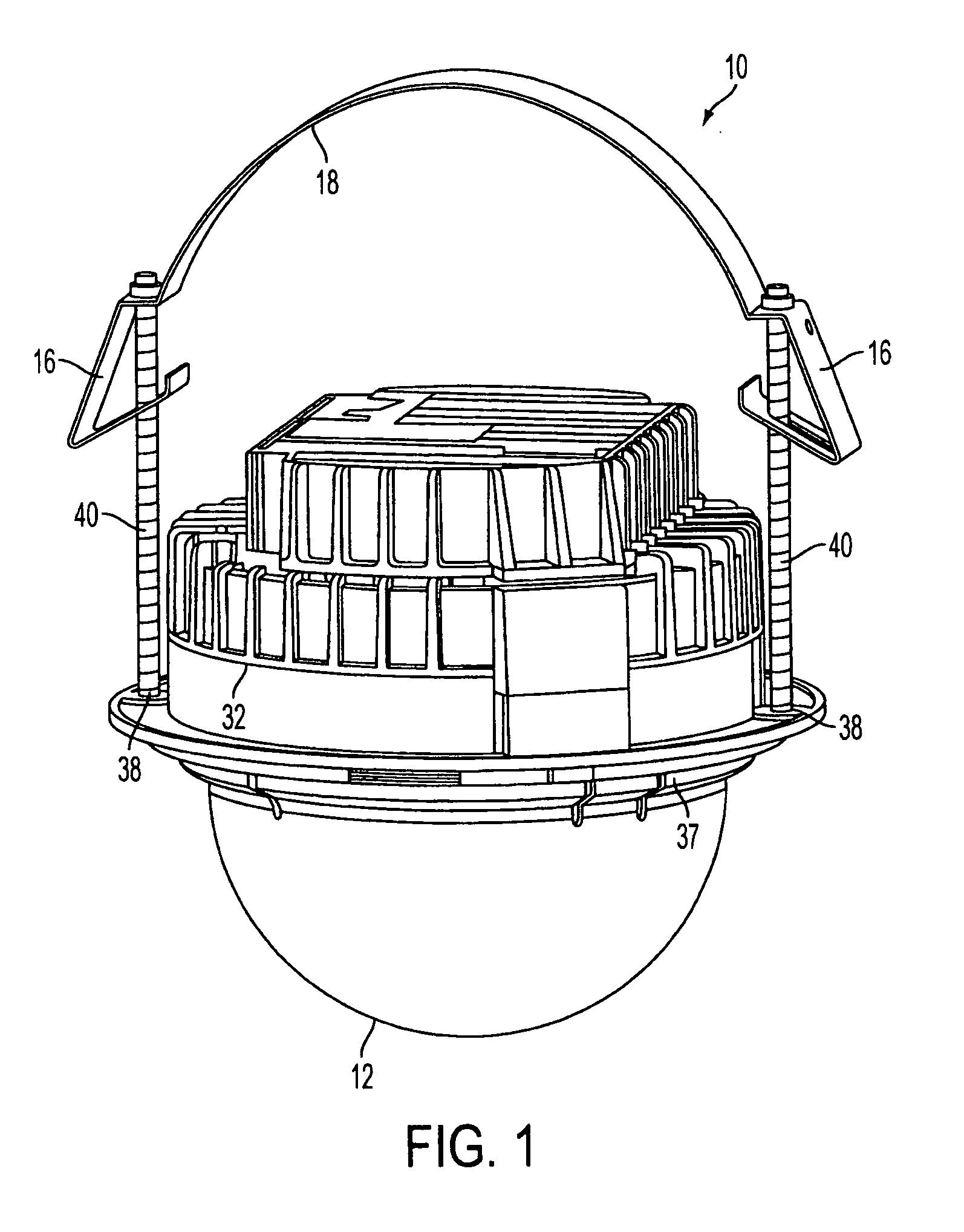
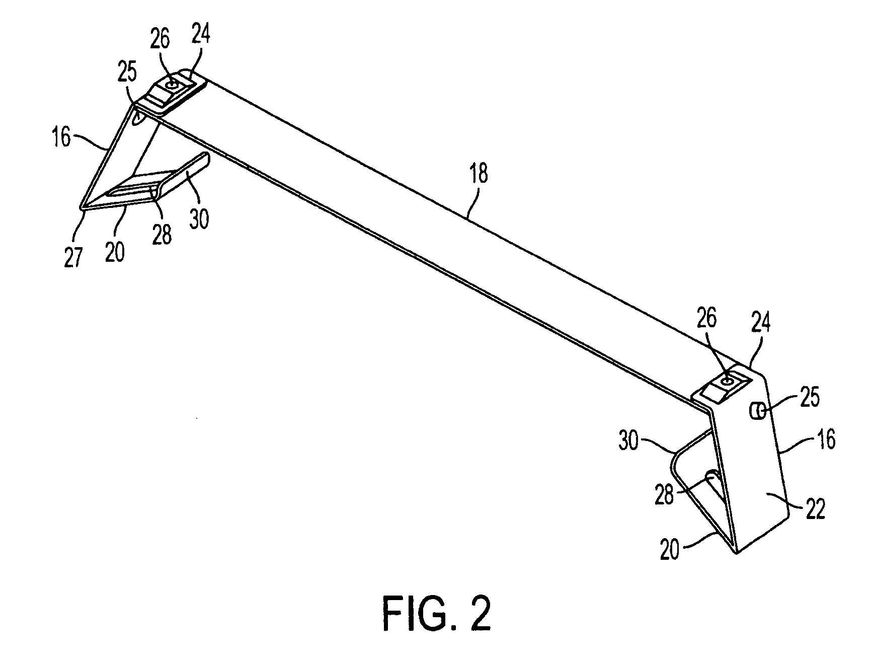
[0014]Referring to FIGS. 1-4, in which like parts have been labeled with like numerals, a mounting assembly 10 for mounting a surveillance camera 12 to a support surface 14, such as a suspended ceiling or hollow wall, according to the present invention is disclosed. Mounting assembly 10 has two spring clips 16, which are connected to opposite ends of flexible member 18. Flexible member 18 is stiff enough to prevent spring clips 16 from rotating while allowing each spring clip 16 position to be independently adjusted both horizontally and vertically. The installation and operation of mounting assembly 10 utilizing the foregoing features will described below in detail. Flexible member 18 can be made of a strip of polypropylene, such as FORMEX GK-30 available from Fabri-Tech Components Inc. located in Fremont, Calif. or other suitable material. Spring clips 16 can be connected to flexible member 18 by various methods such as gluing, bonding, or multiple fasteners.

[0015]Each spring clip...


PUM


Abstract

An apparatus for mounting a recessed electric fixture in a hole in a support surface having a housing and flexible member with attached spring clips to secure the housing against the support surface is disclosed. The flexible member and spring clips are attached to the recessed electric fixture by tightening members, and inward pressure applied to the tightening members causes the flexible member to bend so that the spring clips are moved inwardly towards the housing, allowing the spring clips and the flexible member to pass through the hole in the support surface. The flexible member unbends when the pressure on the tightening members is removed, allowing the spring cops to move outwardly from the housing so that a surface-bearing section of the spring clips bears against the back side of the support surface and retains the electric fixture in the support surface hole.

Description

CROSS-REFERENCE TO RELATED APPLICATION[0001]N / ASTATEMENT REGARDING FEDERALLY SPONSORED RESEARCH OR DEVELOPMENT[0002]N / ABACKGROUND OF THE INVENTION[0003]This invention relates generally to surveillance systems and, in particular, to an assembly for mounting video cameras.[0004]Surveillance system cameras have been installed in many different environments. When the installation has required a recessed mount, the cameras have been installed in recessed-mounted canisters (commonly called “back boxes” in the industry). The back boxes are typically attached by screws, bolts and so forth directly to structural elements, such as beams and joists, that are located above or behind the ceiling or wall to which the camera is to be mounted. This type of mounting requires access to the structural elements, which is frequently not available and requires that the structural elements be located at an appropriate distance from the ceiling or wall to accommodate the size of the back box.[0005]U.S. Pat...

Claims


Application Information

Patent Timeline
Patent Type & Authority Patents(United States)
IPC IPC(8): B42F13/00
CPCG08B13/19619H04N5/2252F21V21/04H02G3/20H04N23/51
Inventor FOREMAN, WILLIAM L.
Owner PELCO INC
Why Eureka
Try Eureka