Clamp for securing components

a technology for fixing components and components, applied in the field of fixing components, can solve the problems of corroding linear elements to be fixed in position, damage to pertinent string-shaped components, and corroding of linear elements, etc., and achieve the effect of inhibiting corrosion

Inactive Publication Date: 2013-10-08
HYDAC ACCESSORIES
View PDF8 Cites 8 Cited by
  • Summary
  • Abstract
  • Description
  • Claims
  • Application Information

AI Technical Summary

Benefits of technology

[0006]An object of the invention is to provide a clamp able to effectively inhibit corrosion and, in particular, crevice corrosion between it and the linear component that is to be held.
[0008]Therefore, the invention provides a clamp that permanently prevents the material from being corroded and inhibits a progressive weakening of the material of every component that is to be secured with the clamp. The system that is the tertiary component and that is fitted with the clamps according to the invention is permanently protected against operating impairments or failure due to the corrosive attack on its string-shaped components, e.g., pipelines, cables, and the like. A high operating reliability of the system is also made possible by the clamp according to the invention.
[0011]In an especially preferred embodiment, the sacrificial element conforms to the cup-shape of the clamp part and does not project beyond the edges of the cup-shaped depression of the clamp, thus saving installation space.

Problems solved by technology

The static or dynamic loads (vibrations) can cause damage to the pertinent string-shaped components.
Especially when clamps are used in a corrosive environment, for example, when they are used in electrical or hydraulic systems in the offshore area, the linear elements to be fixed in position, like the stainless steel pipes, may corrode even with the use of plastic clamps, used to secure the stainless steel pipes, because of the environmental influences, like salt air and the like.
Hence, the result is typically crevice corrosion at the metal parts in the presence of a corrosive medium in unsealed support crevices, for example, affixed cross pieces formed by overlappings, and welds at joining points with no root penetration.
The result of the indicated concentration differential is a potential difference leading to electrochemical corrosion inside the crevice or in the area of the environment of the crevice.

Method used


Image

  • Clamp for securing components
  • Clamp for securing components
  • Clamp for securing components

Examples


Embodiment Construction

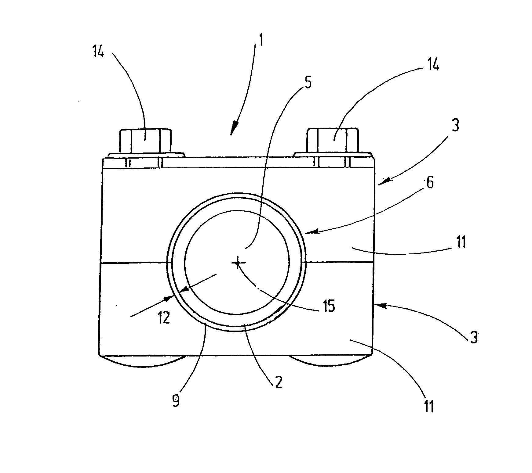
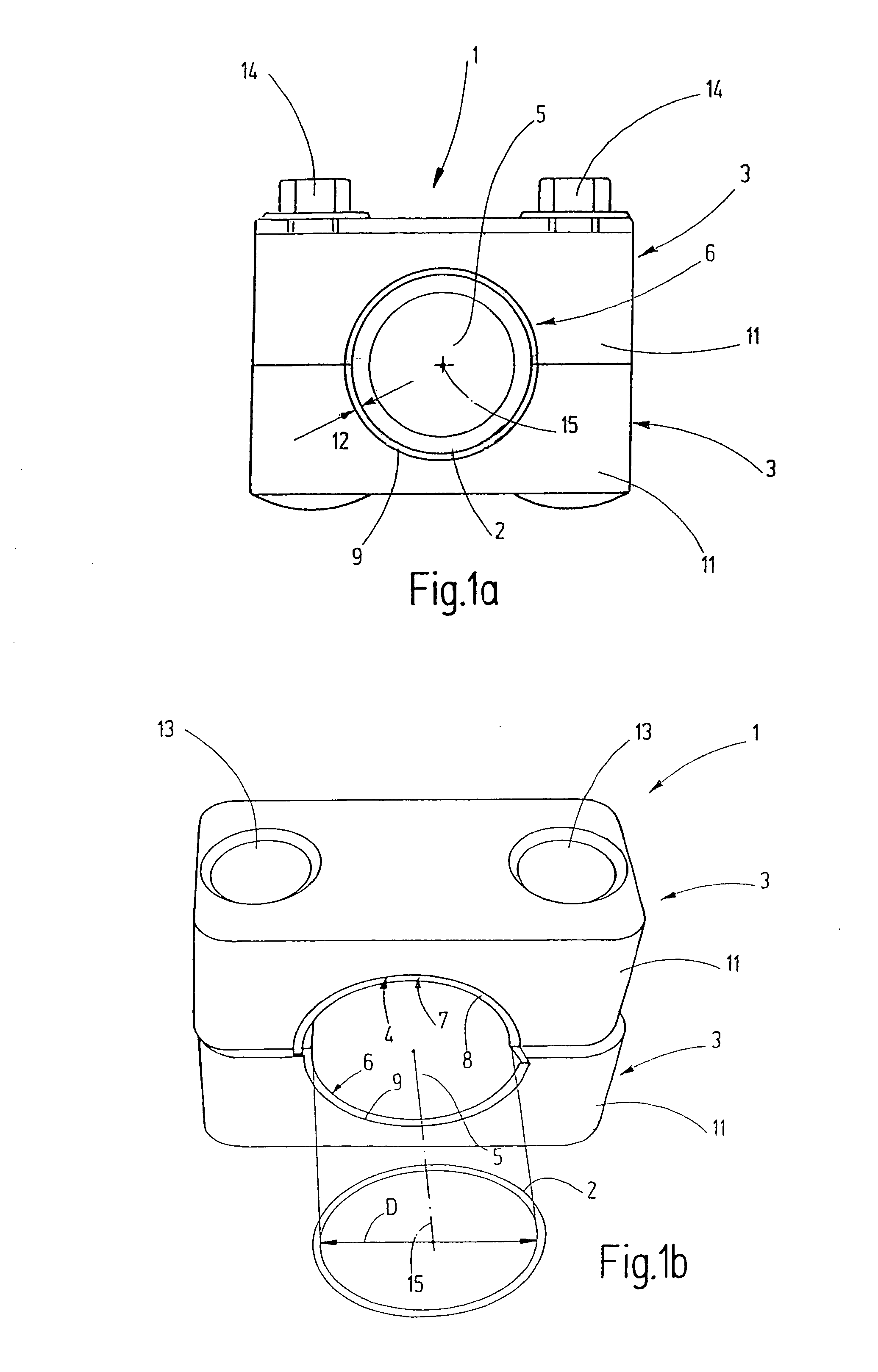
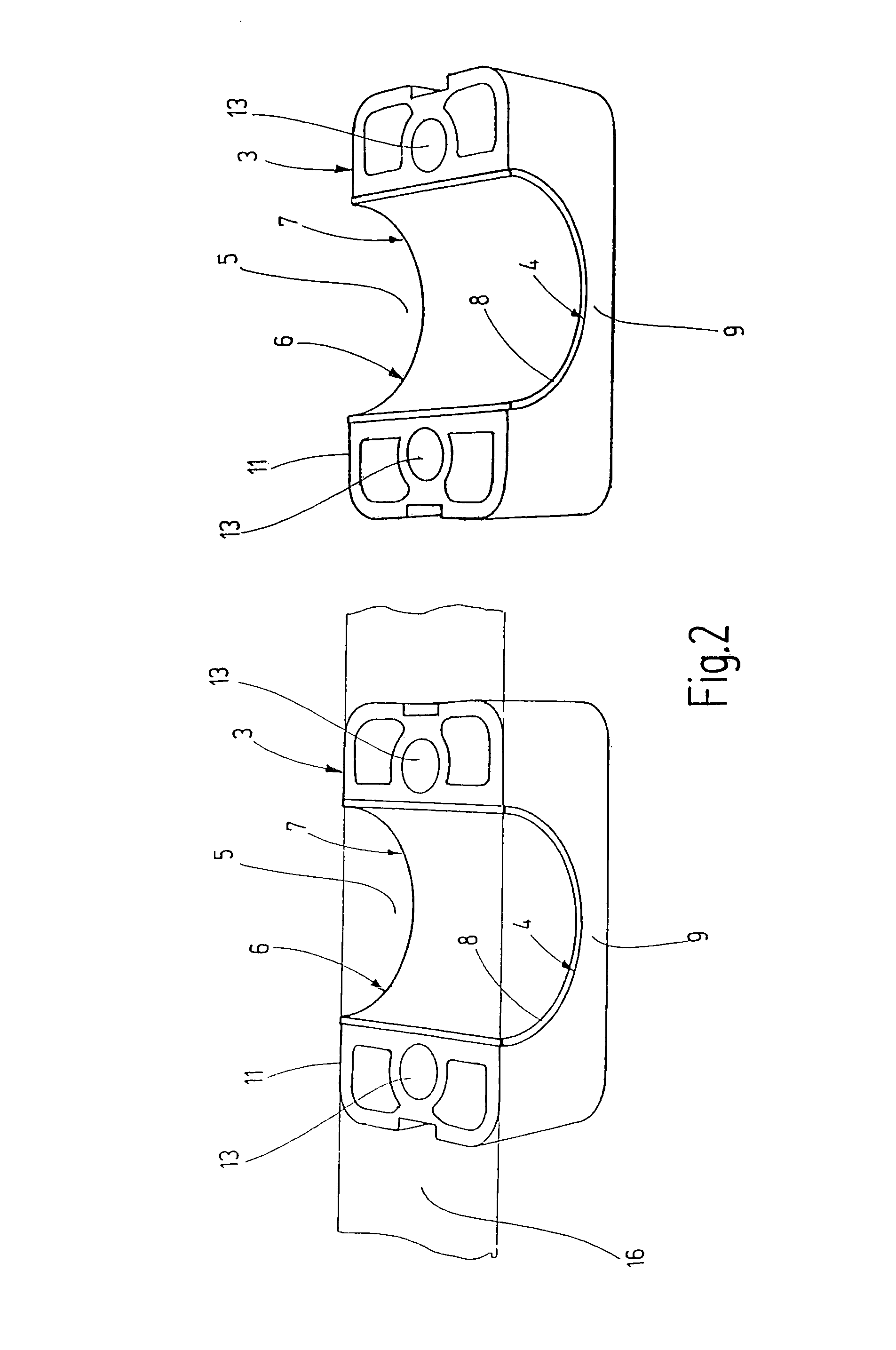
[0023]FIG. 1a is a schematic view (not drawn to scale) of an inventive clamp 1 shown in the closed state and intended for securing a structural member 2 constructed as a CrNi steel pipe and a component of a hydraulic offshore system. The clamp 1 consists essentially of injection molded clamp parts 3, made of a thermoplastic material, in this case in the form of a polypropylene plastic. The clamp parts 3 are configured, as also shown in FIG. 2, as identical components having an essentially rectangular outer plan form. Thus, the overall form of the clamp 1 is cuboid. In this case FIG. 1a shows that a receiving space 5 in the form of a hollow cylinder is formed by the two assembled clamp parts 3. When the clamp 1 is in the divided state, as shown in FIG. 1a, the receiving space 5 for the structural member 2 to be secured is formed by a semi-cylindrically shaped part or a cup-shaped depression 9 in each clamp part 3. The cup-shaped depressions 9 are configured to be symmetrical relative...


PUM


Abstract

A clamp for securing components, in particular string-like or linear structural members, like pipelines, hoses, or cables, has at least one clamp part (3). The clamp part outer contour (4) delimits at least partially a receiving space (5) for receiving the component. The one clamp part (3) has a mechanism (6) for minimizing corrosion, in particular, crevice corrosion, at every component that is held. The mechanism has at least one sacrificial element (7) that is visibly consumed with the onset of corrosion and continued duration of use of the clamp fastener. The respective sacrificial element (7) is placed, as an independent component, on the outer contour (4) of the clamp part (3).

Description

FIELD OF THE INVENTION[0001]The invention relates to a clamp for securing components, in particular string-shaped structural members, e.g., pipelines, hoses, or cables, having at least one clamp part. The clamp outer contour delimits at least partially a receiving space for receiving the respective component. At least one clamp part has a mechanism for minimizing corrosion, in particular, crevice corrosion, at every component that is held.BACKGROUND OF THE INVENTION[0002]In electrical or hydraulic systems, hoses or cables as well as hydraulic lines are connected to system components. The static or dynamic loads (vibrations) can cause damage to the pertinent string-shaped components. In addition, for the sake of a better overview with respect to the interconnection, the hoses, pipelines, and the like should be laid more systematically along commensurate system components. Therefore, the prior art connects the indicated cables and lines by clamps used as spacers and instrumental in se...

Claims


Application Information

Patent Timeline
Patent Type & Authority Patents(United States)
IPC IPC(8): F16L3/08
CPCF16L3/1091H02G3/32C23F13/10C23F13/18C23F2213/32
Inventor HISS, HELMUTCASPARI, JOCHEN
Owner HYDAC ACCESSORIES
Why Eureka
Try Eureka