Apparatus and method for transporting flexible, planar products

a technology of apparatus and planar products, applied in the direction of conveyors, conveyor parts, pile separation, etc., can solve the problems of losing the order arrangement, and achieve the effect of ensuring and reliable product transfer

Inactive Publication Date: 2013-10-08
FERAG AG
View PDF34 Cites 2 Cited by
  • Summary
  • Abstract
  • Description
  • Claims
  • Application Information

AI Technical Summary

Benefits of technology

[0004]An object of the present invention is therefore to provide an apparatus and a method for transporting flexible, planar products, which apparatus / method ensures a secure and reliable transfer of the products from a gripper conveyor to a belt conveyor, even at high conveying velocities.

Problems solved by technology

In the case of large processing capacities and the high conveying velocities associated therewith, the problem exists that the printed products flap when transferred from the gripper conveyor to the belt conveyor and, in particular, behave erratically after being released by the grippers of the gripper conveyors, with the risk of losing their ordered arrangement.

Method used


Image

  • Apparatus and method for transporting flexible, planar products
  • Apparatus and method for transporting flexible, planar products
  • Apparatus and method for transporting flexible, planar products

Examples


Embodiment Construction

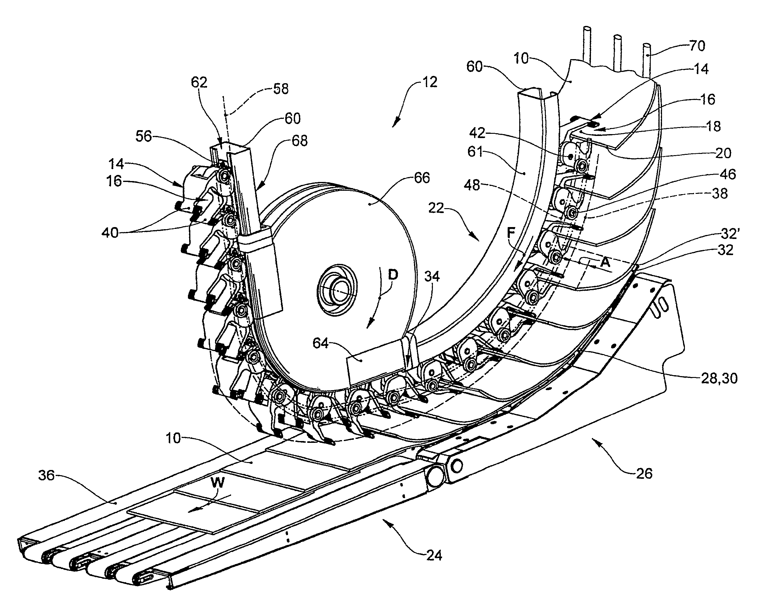
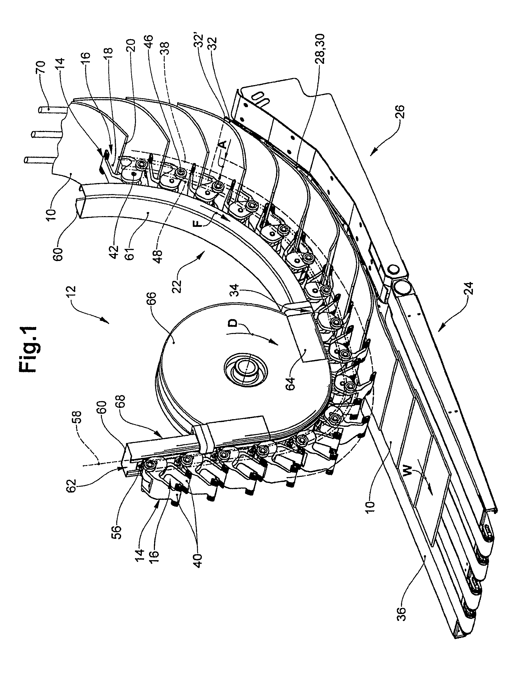
[0048]FIG. 1 shows a region, relating to the present invention, of an apparatus for transporting flexible, planar products 10, in the present case printed products such as newspapers, magazines or the like. It has a gripper conveyor 12, serving as a feed conveyor, whose grippers 14, which are driven rotatingly in a direction of conveyance F and are arranged one behind another, are designed to, with their gripper jaw 16, respectively secure a product 10 by its holding region 18 adjoining a holding edge 20 and transport it to a transfer portion 22.

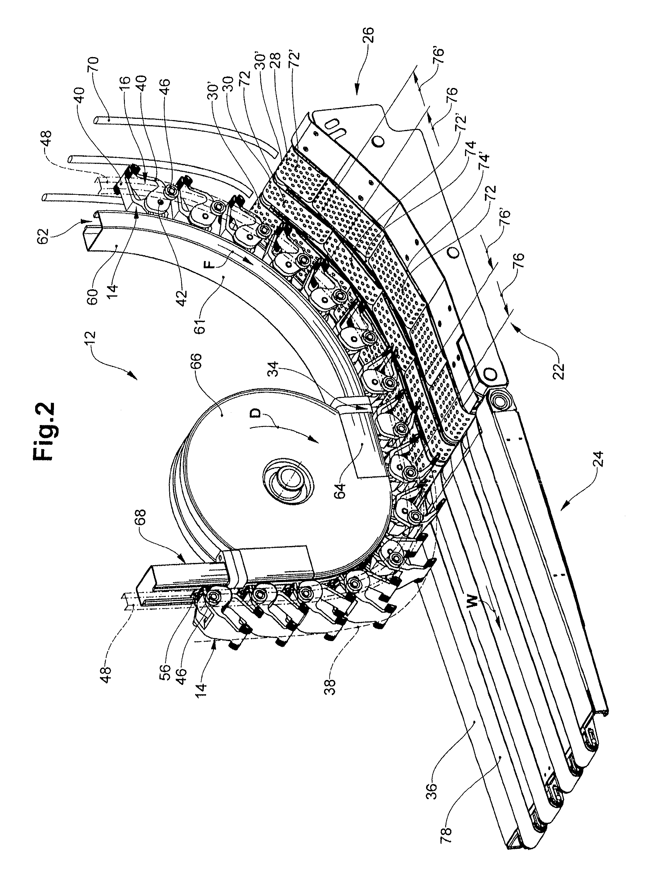
[0049]Arranged downstream of the gripper conveyor 12 is an evacuation conveyor 24 configured as a belt conveyor, which in the transfer portion 22 is configured as a vacuum belt conveyor 26. The vacuum belt conveyor 26, which is disposed in the transfer portion 22 beneath the gripper conveyor 12, is designed to, in the transfer portion 22, with its active strand 28 of the perforated belt 30, which active strand 28 is driven in the direction o...


PUM

PropertyMeasurementUnit
angleaaaaaaaaaa
radiusaaaaaaaaaa
radiusaaaaaaaaaa

Abstract

Printed products (10) are conveyed to a transfer portion (22) by means of the grippers (14) of the gripper conveyor (12). The vacuum belt conveyor (26) suctions with its active strand (28) the respective end region (32) of the printed products (10), after which, close to the end of the (34) of the transfer portion (22), the grippers (14) respectively release the printed products (10). The motional path (38) of the gripper jaws (16) runs in the transfer portion (22) in the shape of an arc. The active strand (28) of the vacuum belt conveyor (26) runs in the transfer portion (22) at an approximately constant distance to the motional path (38). In the case of large processing capacities and correspondingly high velocities, a reliably secure, positionally stable transfer of the printed products (10) from the gripper conveyor (12) to the vacuum belt conveyor (26) is thereby ensured.

Description

CROSS-REFERENCE TO RELATED APPLICATIONS[0001]This application claims priority to Swiss Application No. 2010 0716 / 10, filed May 10, 2010.BACKGROUND OF THE INVENTION[0002]The present invention relates to an apparatus and a method for transporting flexible, planar products, as claimed in patent claims 1 and 13 respectively.[0003]In particular in mailrooms of printing houses, the printed products are frequently transported by means of gripper conveyors. In this context, it frequently happens that the printed products are delivered from the gripper conveyors to the belt conveyor for further processing. In the case of large processing capacities and the high conveying velocities associated therewith, the problem exists that the printed products flap when transferred from the gripper conveyor to the belt conveyor and, in particular, behave erratically after being released by the grippers of the gripper conveyors, with the risk of losing their ordered arrangement.BRIEF SUMMARY OF THE INVENT...

Claims


Application Information

Patent Timeline
Patent Type & Authority Patents(United States)
IPC IPC(8): B65H5/08B65H29/04
CPCB65H29/003B65H29/042B65H29/242B65H29/6609B65H2301/3422B65H2301/44712B65H2301/44735B65H2404/2691B65H2404/2693B65H2405/552B65H2701/1313B65H2701/1932B65H2220/02B65H2220/01
Inventor BERNI, CLAUDIO
Owner FERAG AG
Why Eureka
Try Eureka