Adjustable bicycle handle bar adapter and associated method

a technology of adapter and handle bar, which is applied in the field of bicycle stems to achieve the effects of reducing body strain and discomfort, strong grip, and reducing frictional area

Active Publication Date: 2013-10-08
DRAPER RICHARD
View PDF12 Cites 20 Cited by
  • Summary
  • Abstract
  • Description
  • Claims
  • Application Information

AI Technical Summary

Benefits of technology

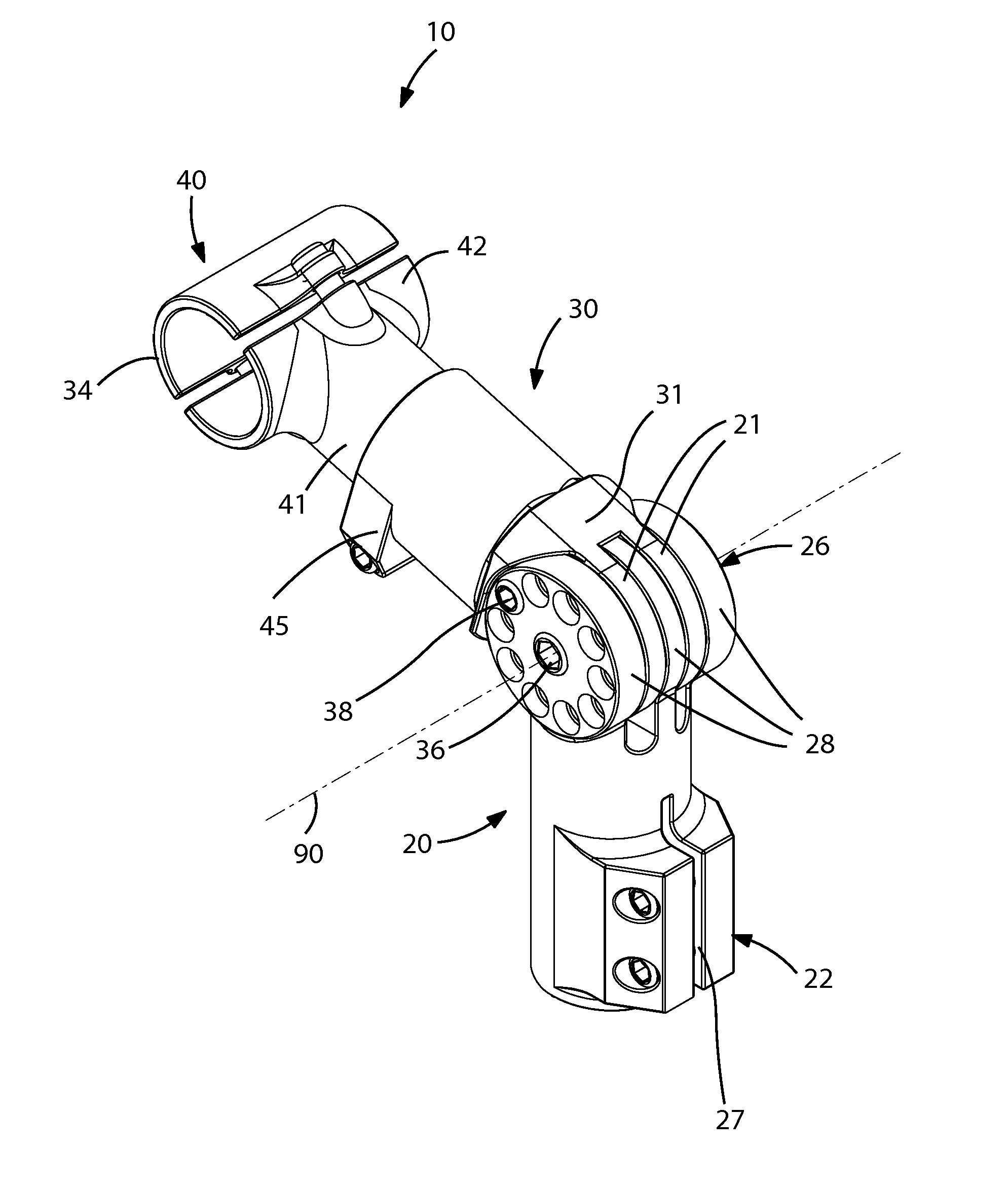
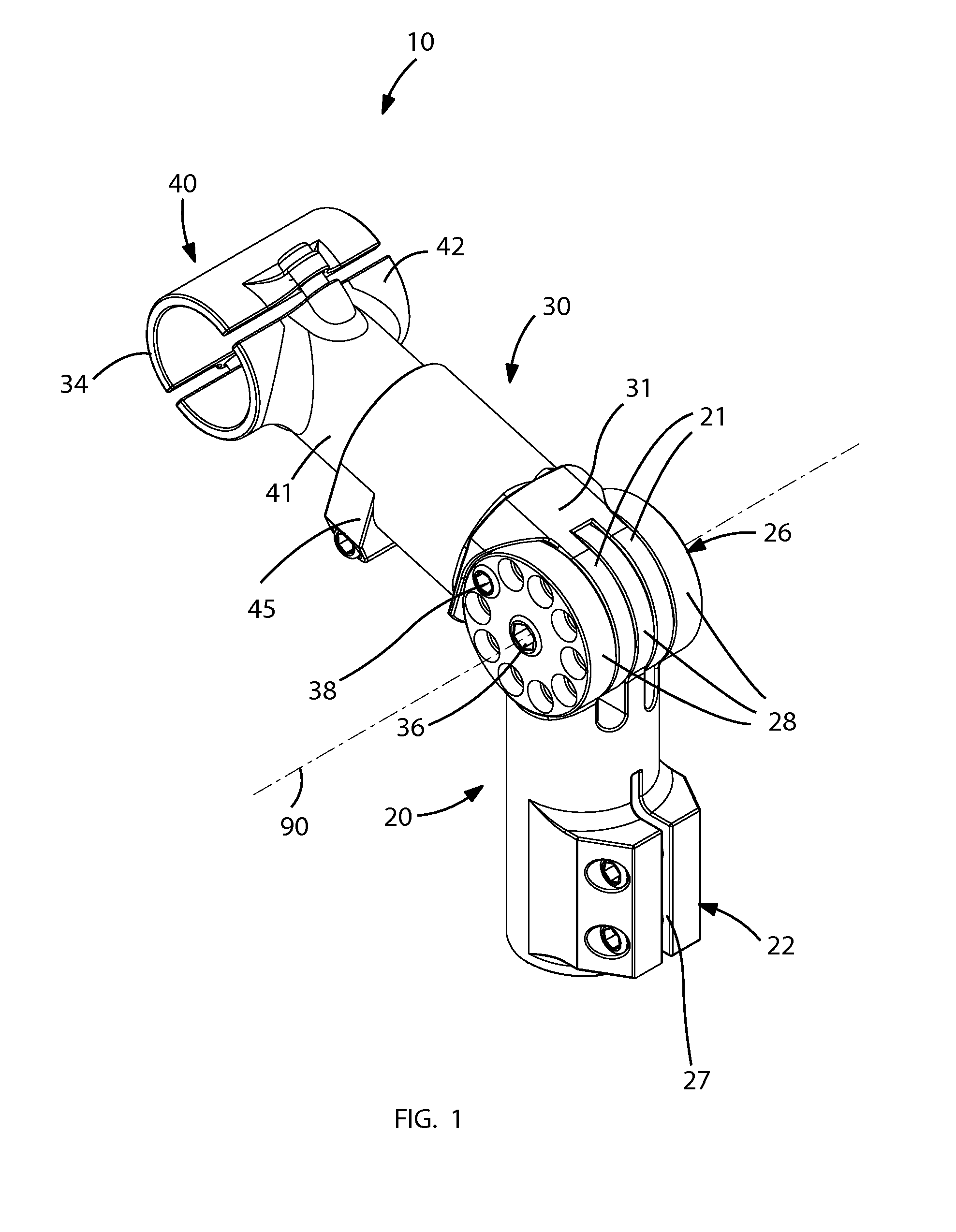
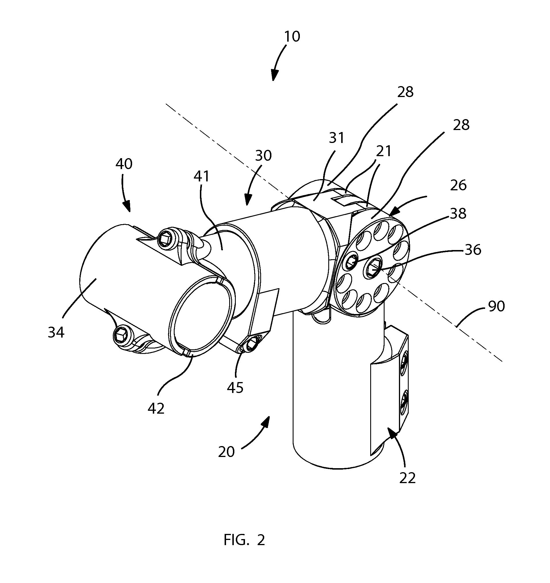
[0011]The bicycle headstock assembly may include a lower member adapted to be attached to a steering rod of the bicycle, and an upper member adjustably connected to the lower member. A pivot joint may be formed at a connection of the lower and upper members respectively. A handle bar clamp may be connected to the upper member and extending away therefrom. A primary fastener may pass through a first location of the pivot joint while an auxiliary fastener may pass through a second location of the pivot joint respectively. In this way, the primary and auxiliary fasteners may cooperate to permit the upper member to selectively pivot and lock at alternate positions relative to the lower member. Such an arrangement provides the unexpected and unpredictable advantage of providing a multiple of height and reach adjustments of the bicycle handle bar vis-à-vis the rider's size. The pivot joint further allows the upper member to be angularly adjusted to suit a variety of different riding styles and comfort.
[0012]The pivot joint may include a plurality of first annular plates statically attached to a proximal end of the upper member and spaced apart at a fixed spatial distance. A plurality of second annular plates may further be statically attached to an upper end of the lower member and spaced apart at a fixed spatial distance respectively. The first annular plates may be rotatably interfitted between the second annular plates respectively such that the first and second annular plates are juxtaposed side-by-side in a parallel configuration. The first and second annular plates may further be co-axially aligned along a fulcrum axis of the pivot joint. Such an arrangement provides the unexpected and unpredictable advantage of enabling a strong grip between the lower and upper members by providing a bigger frictional area between the first and second annular plates respectively.
[0013]The first and second annular plates may be provided with a primary aperture formed at a center thereof and aligned along the fulcrum axis of the pivot joint. Each of the first and second annular plates may further be provided with a plurality of auxiliary apertures formed along a circumference thereof respectively, such that corresponding ones of the auxiliary apertures may be aligned along a plurality of linear paths registered parallel to the fulcrum axis of the pivot joint. In this way, the primary fastener may be removably interfitted through each of the primary apertures and thereby pivotally engages the upper member to the lower member respectively. The auxiliary fastener may further be removably interfitted through the corresponding auxiliary apertures and thereby statically engages the upper member to the lower member. In this way, removal of the auxiliary fastener from the pivot j

Problems solved by technology

The effects of carpal tunnel syndrome are well known by cyclists due to the wr

Method used


Image

  • Adjustable bicycle handle bar adapter and associated method
  • Adjustable bicycle handle bar adapter and associated method
  • Adjustable bicycle handle bar adapter and associated method

Examples


Embodiment Construction

[0035]The present invention will now be described more fully hereinafter with reference to the accompanying drawings, in which a preferred embodiment of the invention is shown. This invention may, however, be embodied in many different forms and should not be construed as limited to the embodiment set forth herein. Rather, this embodiment is provided so that this application will be thorough and complete, and will fully convey the true scope of the invention to those skilled in the art. Like numbers refer to like elements throughout the figures.

[0036]The illustrations of the embodiments described herein are intended to provide a general understanding of the structure of the various embodiments. The illustrations are not intended to serve as a complete description of all of the elements and features of apparatus and systems that utilize the structures or methods described herein. Many other embodiments may be apparent to those of skill in the art upon reviewing the disclosure. Other ...


PUM


Abstract

A bicycle headstock assembly may include a lower member adapted to be attached to a steering rod of the bicycle, and an upper member adjustably connected to the lower member. A pivot joint may be formed at a connection of the lower and upper members respectively. A handle bar clamp may be connected to the upper member and extending away therefrom. A primary fastener may pass through a first location of the pivot joint while an auxiliary fastener may pass through a second location of the pivot joint respectively. In this way, the primary and auxiliary fasteners may cooperate to permit the upper member to selectively pivot and lock at alternate positions relative to the lower member.

Description

CROSS REFERENCE TO RELATED APPLICATIONS[0001]This application claims the benefit of U.S. Provisional Application No. 61 / 236,906, filed Aug. 26, 2009, the entire disclosures of which are incorporated herein by reference.STATEMENT REGARDING FEDERALLY SPONSORED RESEARCH OR DEVELOPMENT[0002]Not Applicable.REFERENCE TO A MICROFICHE APPENDIX[0003]Not Applicable.BACKGROUND OF THE INVENTION[0004]1. Technical Field[0005]This invention relates to bicycle stems and, more particularly, to a bicycle headstock assembly for providing users with an effective means of easily adjusting the height and reach of a bicycle handlebars.[0006]2. Prior Art[0007]Ergonomically, all human beings are of differing physical geometry. When any person male or female purchases a “standard” bicycle of any make, the comfort fit due to the standard frame geometry and standard no / limited-adjustable components is a compromise due to the standard design of the bicycle.[0008]The structural design of a conventional handlebar...

Claims


Application Information

Patent Timeline
IPC IPC(8): B62K21/16
CPCB62K21/16
Inventor DRAPER, RICHARD
Owner DRAPER RICHARD
Why Eureka
Try Eureka