Variable mechanical-impedance artificial legs

a mechanical parameter and artificial leg technology, applied in the field of robotics of the legs, orthotic leg devices, prosthetic leg joints, etc., can solve the problems of inability to restore normal levels of ankle powered plantar flexion, inability to achieve normal biological levels, and simple linear or non-linear spring action cannot adequately mimic a natural limb. achieve the effect of increasing the number of pneumatic springs in parallel and reducing power consumption

Inactive Publication Date: 2013-10-08
OTTO BOCK HEALTHCARE IP GMBH & CO KG
View PDF415 Cites 69 Cited by
  • Summary
  • Abstract
  • Description
  • Claims
  • Application Information

AI Technical Summary

Benefits of technology

[0026]Several variable-stiffness embodiments are described herein in which variable spring-rate structures are constructed by varying the length of a moment arm which attaches to a spring element about a pivot axis, thus providing a variable rotational spring rate about the pivot axis. Examples of such embodiments are depicted in FIGS. 9 through 11. In a preferred embodiment, variations in the length of the moment arm are made under microprocessor control at times of zero load, to minimize power consumed in the active control system.
[0027]Variable-stiffness embodiments of the present invention employing multiple interlockable parallel spring elements are depicted in FIGS. 12 through 14. In FIGS. 12a and 12b, multiple parallel elastic leaf spring elements undergo paired interlocking at pre-set joint flexures or under microprocessor control. This embodiment makes possible arbitrary piecewise-linear approximations to non-linear spring functions (such as function 624 in FIG. 12d). A pneumatic embodiment which can be configured to behave similarly to the leaf spring embodiments shown in FIGS. 12a and 12b is shown in FIG. 13. In the pneumatic embodiment of FIG. 13, valves are electronically closed to effectively increase the number of pneumatic springs in parallel.

Problems solved by technology

Although these systems restore a high level of functionality to leg amputees, they nonetheless fail to restore normal levels of ankle powered plantar-flexion, a movement considered important not only for biological realism but also for walking economy.
Although some power plantar-flexion is possible with these elastic systems, normal biological levels are not possible.
Unfortunately, any simple linear or non-linear spring action cannot adequately mimic a natural limb that puts out positive power during part of the gait cycle.

Method used


Image

  • Variable mechanical-impedance artificial legs
  • Variable mechanical-impedance artificial legs
  • Variable mechanical-impedance artificial legs

Examples


Embodiment Construction

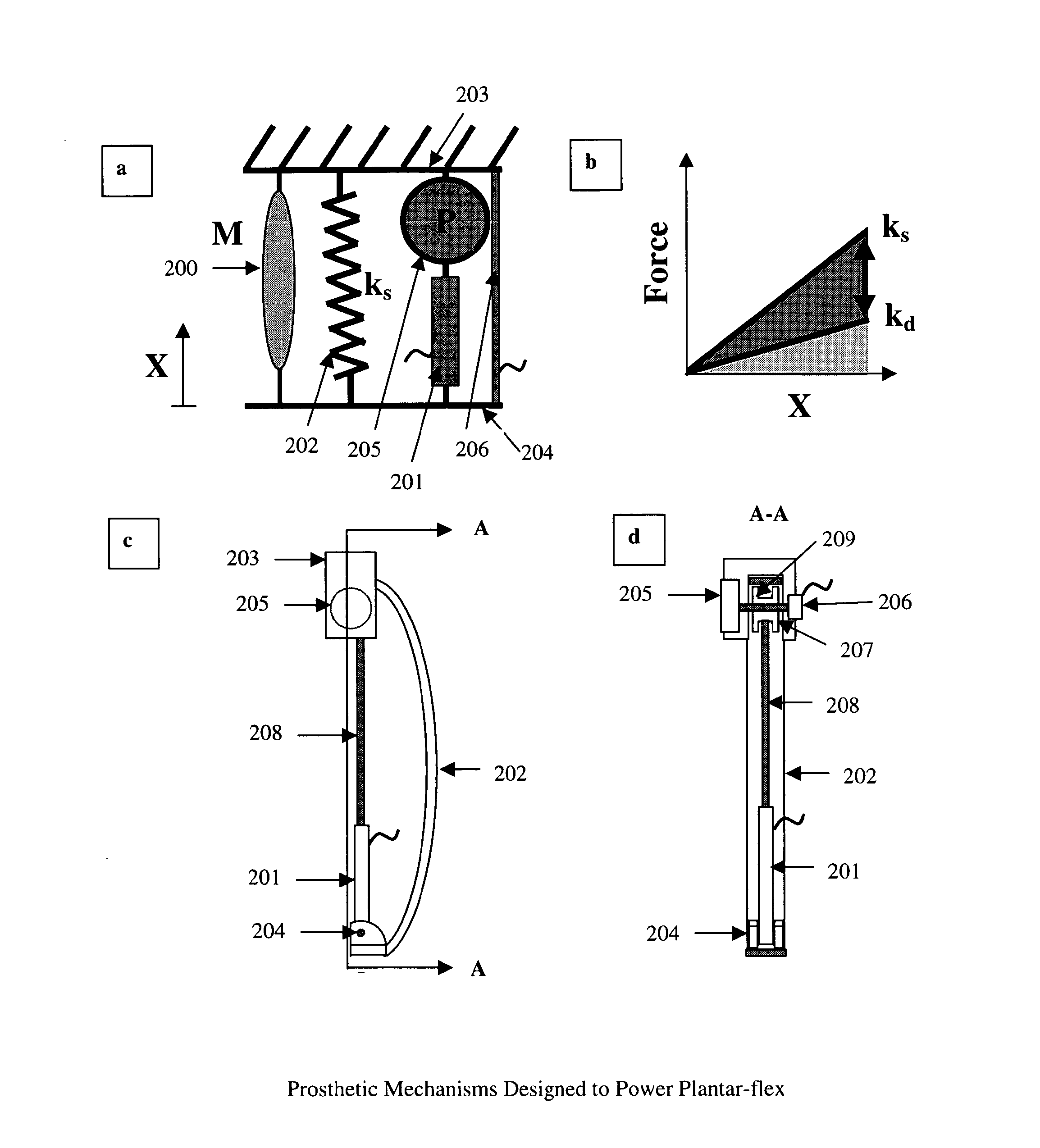
[0055]A powered-catapult embodiment of the present invention is shown in FIGS. 4a-4d. FIG. 4a is a lumped-element model of a powered-catapult prosthetic. The mounted end 203 of the prosthesis attaches to the body, and the distal end 204 of the prosthesis interfaces to the environment (such as the ground for a leg prosthesis). Mounted end 203 is coupled to distal end 204 through spring 202, and through the series combination of force actuator 205 and force sensor 201. In some embodiments, displacement sensor 206 may also be included in parallel with spring 202. If the system is designed to operate in parallel with an existing limb, the muscles of the existing limb are modeled by muscle 200.

[0056]A mechanical implementation of lumped-element diagram 4a is shown in side view in FIG. 4c and in front view in FIG. 4d. In a preferred embodiment, during the portion of a gait cycle when the foot is not in contact with the ground, motor 205 turns spool 209 to wind on some of tension band 208,...


PUM


Abstract

In one aspect, the invention provides methods and apparatus facilitating an adjustable-stiffness prosthesis or orthosis (including approximations to arbitrarily definable non-linear spring functions). Spring rates may be varied under no-load conditions during a walking gate cycle to minimize power consumption. In another aspect, the invention provides methods and apparatus for outputting positive power from a prosthesis or orthosis, facilitating high-performance artificial limbs. In one embodiment of the invention, the positive power is transferred from a functioning muscle to the prosthesis or orthosis, which mimics or assists a non-functioning or impaired muscle. In another embodiment of the invention, the positive power comes from an on-board power source in the prosthesis or orthosis.

Description

CROSS-REFERENCE TO RELATED APPLICATIONS[0001]This application is a continuation of U.S. application Ser. No. 10 / 613,499, filed on Jul. 3, 2003, which claims priority to U.S. Application Ser. No. 60 / 395,938, filed on Jul. 15, 2002, and incorporates by reference those applications in their entirety and claims priority thereto.FIELD OF THE INVENTION[0002]The invention relates generally to the fields of legged robotics, orthotic leg devices and prosthetic leg joints, and more specifically to artificial limbs with time-variable mechanical parameters.BACKGROUND[0003]Prosthetic limbs have come a long way since the days of simple wooden “peg legs”. Today, amputee men running on a prosthetic leg can beat race times of the best unimpaired women runners. It is believed that new advances in prosthetic limbs (such as those embodied in the present invention) will soon lead to amputees being able to out-perform the best unimpaired athletes of the same sex in sports such as running. It is an object...

Claims


Application Information

Patent Timeline
Patent Type & Authority Patents(United States)
IPC IPC(8): A61F2/70A61F2/66A61F2/50A61F5/01
CPCA61F2/66A61F5/01A61F2/60A61F2/6607A61F2002/5007A61F2002/503A61F2005/0169A61F2002/6621A61F2005/0134A61F2002/6845A61F2002/5033A61F2/602A61F2/64A61F2002/6614A61F2/74
Inventor HERR, HUGH M.
Owner OTTO BOCK HEALTHCARE IP GMBH & CO KG
Why Eureka
Try Eureka