Hybrid electric power for vehicular propulsion

a hybrid electric power and vehicular propulsion technology, applied in the direction of electric generator control, electric motor propulsion transmission, instruments, etc., can solve the problems of exhaust emissions, limited tin fuel use selection, and reduced cycle efficiency, so as to improve fuel use and extend the range

Active Publication Date: 2013-10-08
TEETAB JOSEPH MICHAEL +1
View PDF11 Cites 44 Cited by
  • Summary
  • Abstract
  • Description
  • Claims
  • Application Information

AI Technical Summary

Benefits of technology

[0009]In view of the foregoing disadvantage inherent in the know type of hybrid vehicular propulsion now present in the prior art, the present invention provides a new invention a Hybrid Gas Turbine (HGT) for hybrid vehicular propulsion system for electrical powered vehicles having at least two electrical power sources, one being a Hybrid Gas Turbine and another a battery pack (stored electrical energy); either in combination or separately supplying electric power to at least one electric motor—prime mover vehicular propulsion to extend the range and improve fuel use without emissions issue and or the complexity of staged fuel injection or combustion variable geometry common to single shaft / single spool microturbines.
[0018]Another object is to provide a hybrid gas turbine for vehicular propulsion that uses a HGT as an electrical power source in the hybrid propulsion system offers compactness, light and high power density (high power to weight ratio), fast response electrical output power, is electrically coupled to the drive motor prime mover for vehicle propulsion, offering simplicity, multifuel and maintenance free engine (high reliability).
[0019]Another object is to provide a HGT for vehicular propulsion as an electrical powerplant that yield improved fuel economy at off design power vehicle cruise power conditions.
[0020]Another object is to provide a HGT for vehicular propulsion that as an internal combustion engine, has low emission combustion without staged fuel delivery or variable combustion geometry. Also because of only 2 moving parts offers high durability over the prior art along with the no separate liquids of cooling.
[0021]Another object is to provide a HGT for vehicular propulsion that HGT is without a weighty, life limited, expensive recuperator typical to the single spool microturbines.

Problems solved by technology

The main problem with conventional hybrid-vehicular propulsion are the piston type internal combustion engine (4 stroke or 2—gasoline engine) of a hybrid vehicle incorporate a clutch engaged gearbox driven generator for electrical output power and or use direct clutch mechanical drive to the differential all of which are complex, weighty, bulky, engine cycle efficiency drops considerably below design (max. power output) operation, has exhaust emissions requiring post combustion treatment, is a complex engine assembly, requires separate engine liquid cooling means, is limited tin fuel use selection, has engine and power-train maintenance requirements.
Another problem with conventional hybrid-vehicular propulsion are piston type internal combustion engines including the Atkinson cycle clutch engaged generator for electrical output power has so some improvement in cycle efficiency but is also weighty and complex, bulky, cycle efficiency greatly reduced at off design conditions, has complex intake valve phasing can to crankshaft, maintenance requirements, requires ignition controls to avoid detonation issues, engine response is slow, has limited fuel use, requires, post combustion exhaust gas treatment to meet emissions regulations, has many engine components and liquids for cooling the engine.
Another problem with conventional hybrid-vehicular propulsion is the use of diesel engines that have high quantity of engine components, incorporate complex clutch engaged electrical output power generator and or separate drive shaft for output power to the transmission or differential.
Although this engine has improved fuel economy over the gasoline piston engines, it is weighty, complex, bulky, efficiency drops off considerably at of design conditions, is limited in fuel use, requires exhaust gas treatments to meet emission regulation, is complex engine assembly, has high maintenance consideration, requires additional engine liquids for cooling and engine response to accelerate less responsive than gasoline piston engines whereas the hybrid gas turbine can be set with instantaneous acceleration.
While these devices may be suitable for the particular purpose to which they address, they are not as suitable for a Hybrid Gas Turbine vehicular propulsion system for electrical powered vehicles having at least two electrical power sources, one being a Hybrid Gas Turbine and another a battery pack.

Method used


Image

  • Hybrid electric power for vehicular propulsion
  • Hybrid electric power for vehicular propulsion
  • Hybrid electric power for vehicular propulsion

Examples


Embodiment Construction

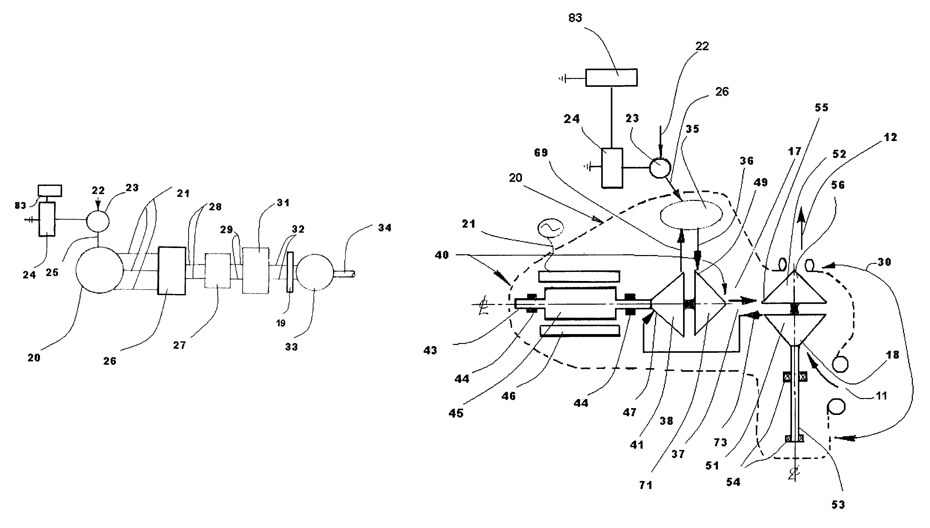
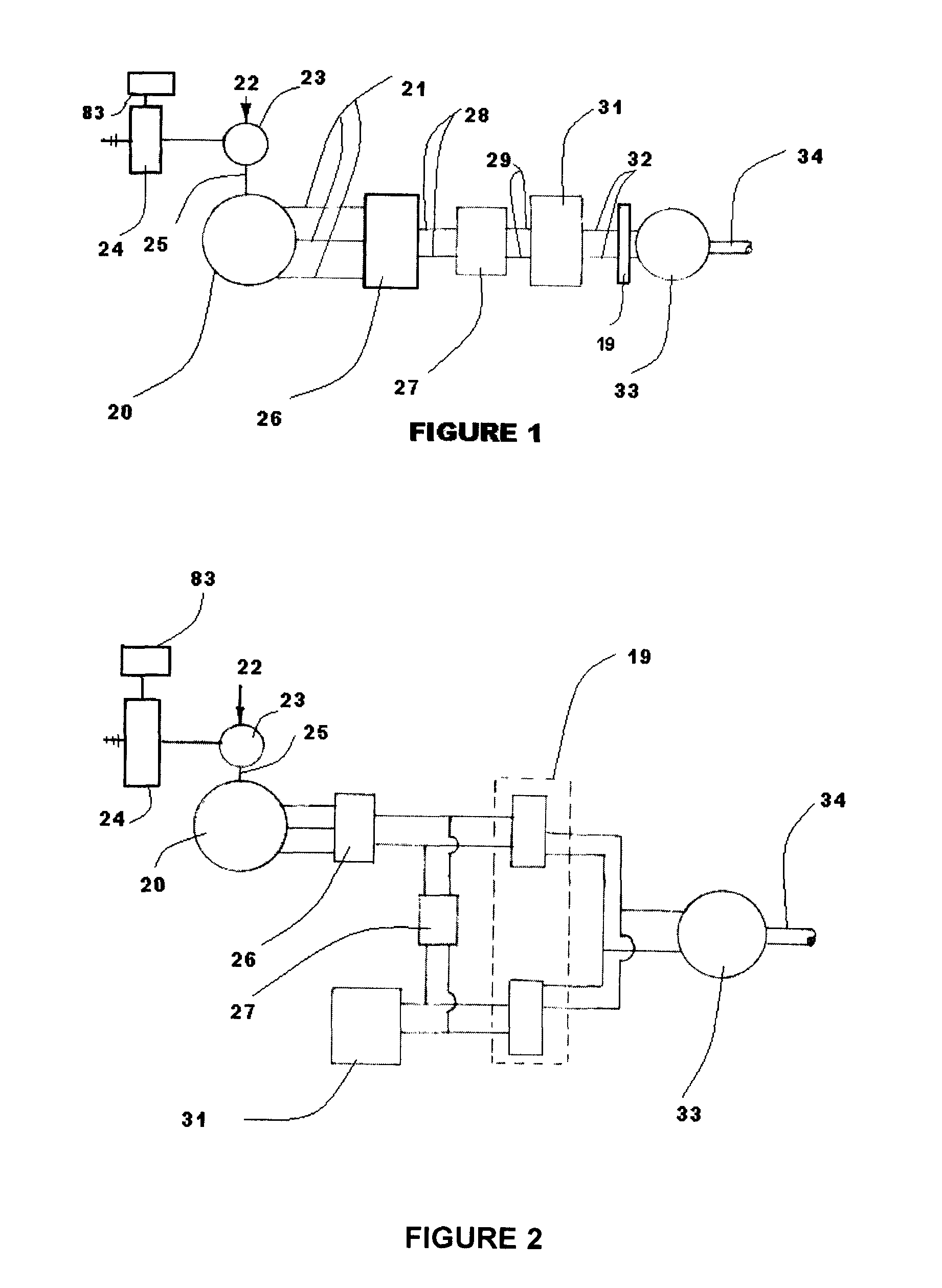
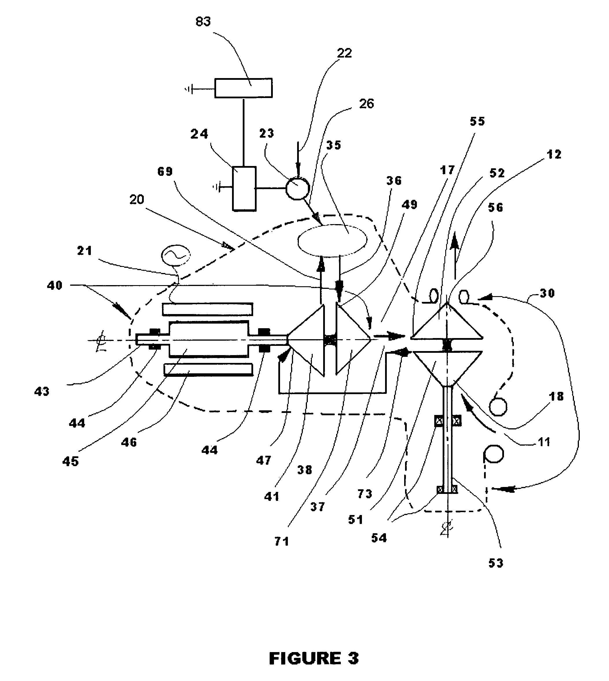
[0032]Turning now descriptively to the drawings, in which similar reference characters denote similar elements throughout the several view, the attached figures illustrate a HGT for vehicular propulsion, which comprises a HGT, Fuel Valve, EECU (electronic engine control unit), Throttle Box, Power Electronics, Battery Pack, Voltage Regulator, Electric Power Source Controller, Power Motor (with controller) and Differential. The HGT is a two spool gas turbine that generates electrical output power; the power output spool N2 integrated alternator rotor, compressor rotor and turbine rotor. An alternator stator is located co-axially about and in close proximity to the alternator rotor. The other spool N1, airflow producer, has a compressor rotor, turbine rotor an rotor shaft with bearings; is compressor / aero coupled to the power spool N2; housed within an engine body and has a combustion means for heat energy to drive the turbine rotors. The Fuel Valve is a electro-mechanical device that ...


PUM


Abstract

This invention relates to a hybrid gas turbine (HGT) engine powerplant having electrical output power and as a system independently or in combination with electrical energy storage means, supplies electrical power to at least one electric motor for vehicular propulsion.The HGT has a minimum of two spools at least one spool, the power spool, has integrated a compressor rotor, turbine rotor and alternator rotor; a minimum second spool for staged engine air compression has integrated a compressor and turbine rotors aero-coupled to the power spool.An electronic engine unit (EECU) supplies electrical power to the fuel control valve, has preprogrammed variable power spool speeds per output power requirements, exhaust gas turbine temperature limits for fuel economy considerations and is responsive thru vehicle throttle commands of accel, decel, constant vehicle operations, start-up, shut down, battery charger and auxiliary power applications (APU).

Description

[0001]The application claims benefit of the provisional application Ser. No. 61 / 516,482 filed Apr. 3, 2011.BACKGROUND OF THE INVENTION[0002]1. Field of the Invention[0003]The present invention relates generally to hybrid vehicular propulsion and more specifically a hybrid gas turbine in a hybrid vehicular electric propulsion system having a minimum of two electrical power sources, one being a Hybrid Gas Turbine (HGT) and the other a battery pack (stored electrical energy means). The electrical power sources can be used in combination either in series or parallel to extend travel range or increase the output power electric power requirements to the electric motor prime mover.[0004]In a stand alone mode either the electric power storage source or hybrid gas turbine engine electrical output power source is used to power the electric motor-prime mover to further extend the travel / mission range and or improve fuel efficiency without combustion emissions compromise. The hybrid gas turbine...

Claims


Application Information

Patent Timeline
Patent Type & Authority Patents(United States)
IPC IPC(8): H02P9/04B60L50/15
CPCG08G1/0129G08G1/012G08G1/0145G01S5/0018H04W28/26H04W64/00
Inventor TEETS, JOSEPH MICHAELTEETS, JON WILLIAM
Owner TEETAB JOSEPH MICHAEL
Why Eureka
Try Eureka