Battery charging coaction and output system with current limit supply

a technology of battery charging and output system, which is applied in the direction of emergency power supply arrangement, instruments, transportation and packaging, etc., to achieve the effect of saving energy

Active Publication Date: 2013-10-08
YANG TAI HER
View PDF3 Cites 5 Cited by
  • Summary
  • Abstract
  • Description
  • Claims
  • Application Information

AI Technical Summary

Benefits of technology

[0005]The present invention relates to a power system utilizing an engine generator or public power with AC source, wherein the power system particularly has the characteristics that the maximum output current thereof is limited by electromagnetic effects, and / or constant current or nearly constant current output thereof is set to be lower than the maximum output current, for powering a load, and charging a battery, or jointly powering a load with a battery; when an engine generator set is utilized to be power supply, during operation, the engine operates with the best brake specific fuel consumption and / or the range of revolutions and torque for better energy saving.

Problems solved by technology

Battery, developed to date, by reason of its convenience for carriage from one place to another and volumetric density, up to utility level, is nowadays frequently used for purpose of emergency power storage, or as a means of power supply to motor driven implements, power driven tooling or more generally as a DC power supply; the pity, however, is that where power supply is required for a prolonged term, or where efforts to enlarge dimensionally a battery would inevitably involve cost increases or weight increases, or still, where exposed to working at a more profound discharge depth the battery would suffer from a shortened service term, improvement to resolve the problems as such is provided in the U.S. Pat. No. 6,831,464 by the inventor, disclosing an engine-driven storage battery auxiliary charging system with automatic monitoring operation functions to adopt engine generator as auxiliary power supply for driving a load motor (or other loads) and timely supporting charging a setting type or vehicle type battery, so as to keep good reserve power status; however, the inventor has found through more subsequent R&D efforts that further improvements as regards the performance feature of the system are made possible to make the entire system more comprehensive and irreproachable.

Method used


Image

  • Battery charging coaction and output system with current limit supply
  • Battery charging coaction and output system with current limit supply
  • Battery charging coaction and output system with current limit supply

Examples


Embodiment Construction

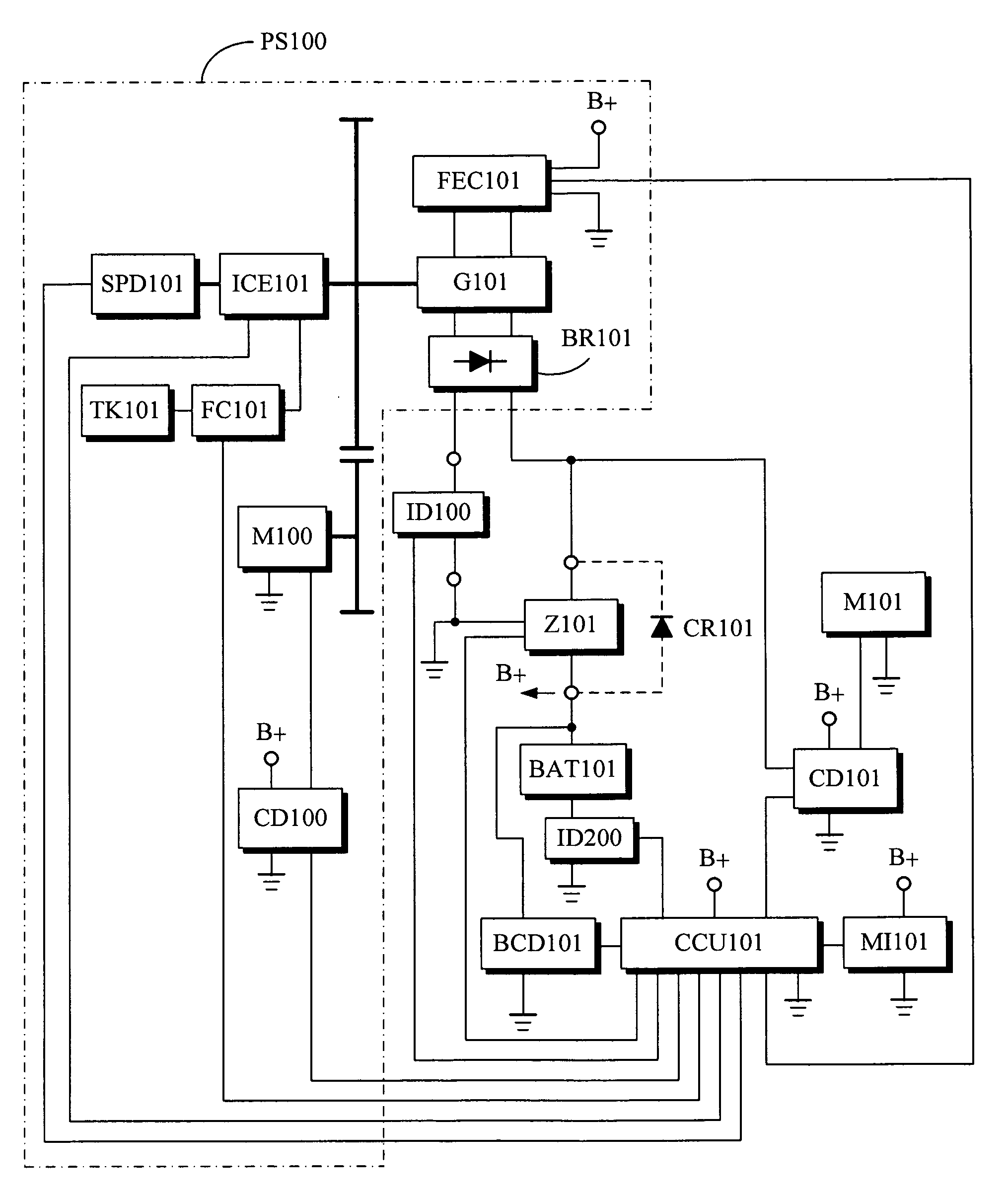
[0038]The battery charging coaction and output system with current limit supply relates to a power system utilizing an engine generator or public power with AC source, wherein the power system particularly has the characteristics that the maximum output current thereof is limited by electromagnetic effects, and / or constant current or nearly constant current output thereof is set to be lower than the maximum output current, for powering a load, and timely supporting charging a setting type or vehicle type battery, or jointly powering a load with a battery; when an engine generator set is utilized to be power supply, during operation, the engine operates with the best brake specific fuel consumption and / or the range of revolutions and torque for better energy saving.

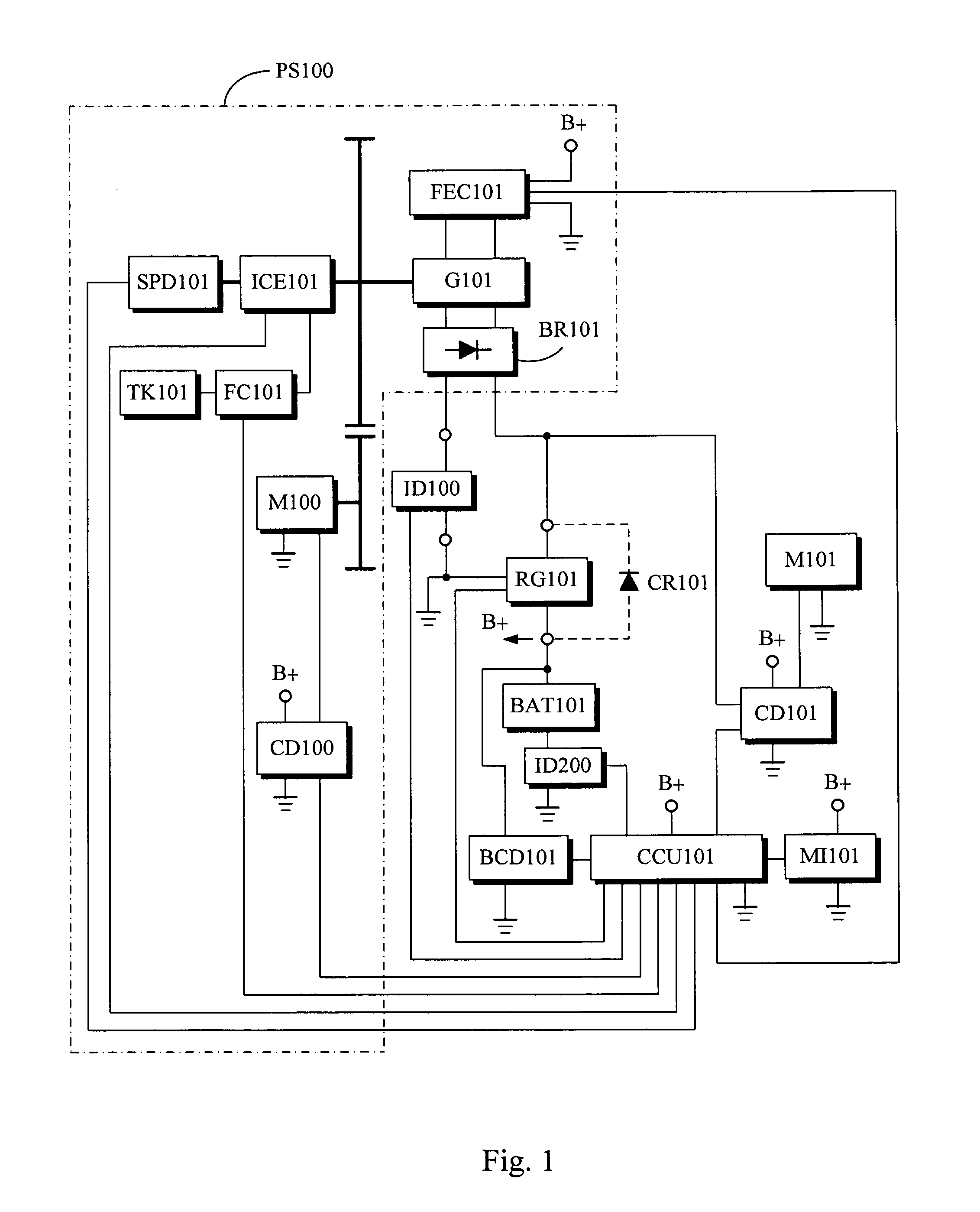
[0039]FIG. 1 is a system block diagram of the battery charging coaction and output system with current limit supply, and the main components are explained as following:

[0040]Battery (BAT101): related to a secondary battery...


PUM


Abstract

The present invention relates to a power system utilizing an engine generator or public power with AC source, wherein the power system particularly has the characteristics that the maximum output current thereof is limited by electromagnetic effects, and / or constant current or nearly constant current output thereof is set to be lower than the maximum output current, for powering a load, and charging a battery, or jointly powering a load with a battery; when an engine generator set is utilized to be power supply, during operation, the engine operates with the best brake specific fuel consumption and / or the range of revolutions and torque for better energy saving.

Description

BACKGROUND OF THE INVENTION[0001](a) Field of the Invention[0002]The battery charging coaction and output system with current limit supply relates to a power system utilizing an engine generator or public power with AC source, wherein the power system particularly has the characteristics that the maximum output current thereof is limited by electromagnetic effects, and / or constant current or nearly constant current output thereof is set to be lower than the maximum output current, for powering a load, and timely supporting charging a setting type or vehicle type battery, or jointly powering a load with a battery; when an engine generator set is utilized to be power supply, during operation, the engine operates with the best brake specific fuel consumption and / or the range of revolutions and torque for better energy saving.[0003](b) Description of the Prior Art[0004]Battery, developed to date, by reason of its convenience for carriage from one place to another and volumetric density,...

Claims


Application Information

Patent Timeline
Patent Type & Authority Patents(United States)
IPC IPC(8): H02J7/34H02J7/04
CPCH02J7/0068H02J7/1438H02J7/34H02J7/04H02J7/1415Y02T10/7005H02J7/007Y02T10/70
Inventor YANG, TAI-HER
Owner YANG TAI HER
Why Eureka
Try Eureka