
Means to reduce a load on a computer and efficiently manage printing jobs or printing devices jobs

a technology of printing device and computer, which is applied in the direction of digital output to print units, instruments, visual presentations, etc., can solve the problem that the cost of a computer is not increased beyond necessity, and achieve the effect of reducing the load of monitoring printing devices or printing jobs and not increasing the cost of a computer

Inactive Publication Date: 2013-10-08
CANON KK
View PDF26 Cites 0 Cited by
  • Summary
  • Abstract
  • Description
  • Claims
  • Application Information

AI Technical Summary

Benefits of technology

[0008]According to the present invention, a monitoring load of monitoring printing devices or printing jobs is reduced even if a plurality of printing device is populated with a large quantity of printing jobs, for example. Therefore, the cost of a computer is not increased beyond necessity.

Problems solved by technology

Therefore, the cost of a computer is not increased beyond necessity.

Method used


Image

  • Means to reduce a load on a computer and efficiently manage printing jobs or printing devices jobs
  • Means to reduce a load on a computer and efficiently manage printing jobs or printing devices jobs
  • Means to reduce a load on a computer and efficiently manage printing jobs or printing devices jobs

Examples


first embodiment

[0040

[0041]The following will describe an embodiment of the present invention with reference to the drawings.

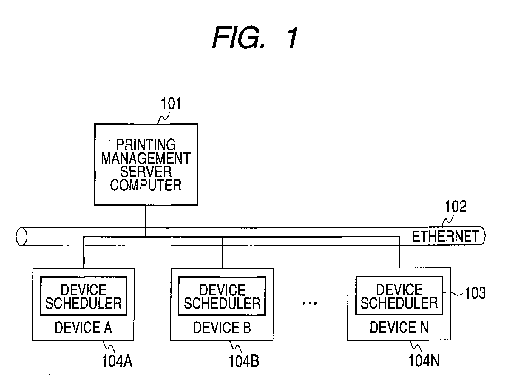
[0042]FIG. 1 is a block diagram illustrating a configuration of a printing system according to the present invention. In the system, a plurality of network printers are connected.

[0043]In FIG. 1, devices 104A, 104B and 104N are printing devices (hereinafter, referred to as “devices”). The printing devices are connected to a network 102 via a network interface (not shown). Each of the devices analyzes a printing job including printed-character data transferred from a printing-management server 101 and converts a dot image page-by-page for printing. A printing job herein is a generic term including drawing data such as a page description language and various types of job setting data for printing characters such as printing layout setting. The devices 104A, 104B and 104N can be a laser beam printer using electronography or an ink-jet printer using an ink-jet system.

[0044]Each o...

second embodiment

[0203

[0204]The maximum number of transferring connections, the maximum number of monitoring connections and the maximum number of connections are decided according to specific numbers being previously set by a user arbitrarily via a setting screen. The maximum number of connections, the maximum number of transferring connections and the maximum number of monitoring connections are changed into set values depending on a printing system environment, so that, setting can be done depending on a system policy to give weight to the monitoring or give weight to the transfer, for example.

[0205]Other Embodiments

[0206]The present invention can be applied to a system including a plurality of machine (for example, host computer, interface machine, reader, printer or the like) or applied to an apparatus including a single machine (for example, copier, facsimile apparatus or the like). The object of the present invention can be accomplished by supplying a recording medium for recording a program ...


PUM


Abstract

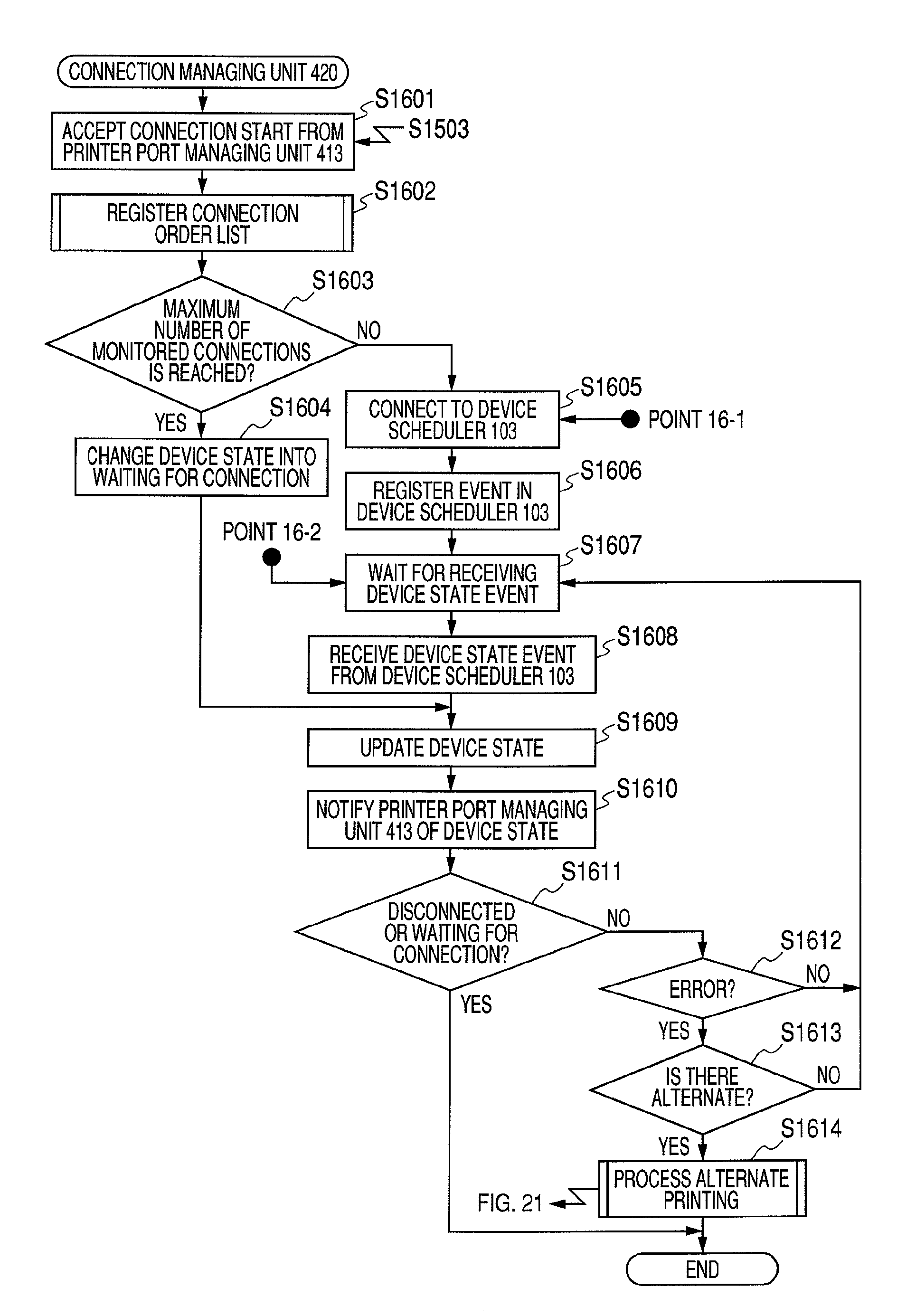
Monitoring of a large number (for example, hundreds) of printing devices in parallel makes a processing load very heavy. Or, the monitoring extremely increases the cost of a monitoring computer. A connection-managing unit sequentially monitors the states of printing devices within the number of connections less than the number of printing devices. Meanwhile, a transfer-managing unit sequentially transfers printing jobs to the printing devices within the number of connections less than the number of printing devices. The state-monitored printing devices are sequentially switched without synchronizing the state monitoring of the printing devices with the end of the transfer of the printing jobs, i.e., without waiting for the end of the transfer of the printing jobs.

Description

BACKGROUND OF THE INVENTION[0001]1. Field of the Invention[0002]The present invention relates to a mechanism to reduce a load on a computer and efficiently to manage printing jobs or printing devices.[0003]2. Description of the Related Art[0004]A distributed printing technique to realize high-speed printing by distributing printing jobs on a network and using a plurality of printer is disclosed in Japanese Patent Application Laid-Open No. 2001-290623. The document discloses that a job issuer such as a personal computer collects the states of the printing jobs distributed to the plurality of printer and the personal computer manages the states of the printing jobs in parallel.[0005]However, for example, a large quantity of printing jobs may be populated for printing to a large number of printing devices on various places connected to a network throughout the country. In order to monitor hundreds of such printing devices, for example, not several printing devices, the monitoring metho...

Claims


Application Information

Patent Timeline
Patent Type & Authority Patents(United States)
IPC IPC(8): G06F3/12
CPCG06F3/1207G06F3/122G06F3/1229G06F3/1236G06F3/1261G06F3/1285H04L67/16H04L67/2814G06F3/1263G06F3/1273H04L67/563H04L67/51G06F3/12G06F15/16
Inventor MATSUGASHITA, HAYATO
Owner CANON KK
Learn More