

Synchronization detecting circuit and automatic synchronous parallelization apparatus
a synchronization detection and automatic synchronization technology, applied in the direction of electrical equipment, single network parallel feeding arrangement, power conversion systems, etc., can solve the problems of not being able to apply a single-phase voltage-type dc-to-ac converting device controlled to be a voltage source, no technology for automatic synchronization, and influence of harmonic components included in a voltage waveform, etc., to avoid overshooting, avoid influence, and reliably maintain stability
- Summary
- Abstract
- Description
- Claims
- Application Information
AI Technical Summary
Benefits of technology
Problems solved by technology
Method used
Image

Examples
example 1
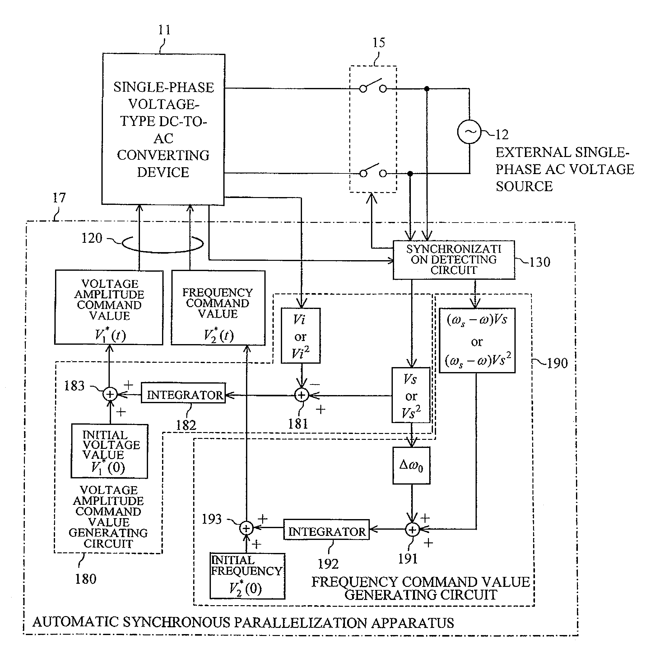
of Automatic Synchronous Parallelization Apparatus
[0191]FIG. 8 is a result of simulating the 1st-axis voltage command value, the 2nd-axis voltage command value, and the single-phase voltage waveform of the single-phase voltage-type DC-to-AC converting device 11 when the automatic synchronous parallelization apparatus 17 connects the single-phase voltage-type DC-to-AC converting device 11 so as to be in parallel with the external single-phase AC voltage source 12.
[0192]It is assumed that the single-phase voltage-type DC-to-AC converting device 11 is operated at 200 V and 50 Hz before a parallelization process. In addition, it is assumed that the external single-phase AC voltage source 12 is operated at 220 V and 54 Hz. At time 80 ms, the coordination command (Step S01) represented in FIG. 6 was performed. Thereafter, the voltage waveform command value slowly increases from 200 V and becomes constant at 240 V (corresponding to an output voltage of 220 V). In accordance with the voltag...
example 2
of Automatic Synchronous Parallelization Apparatus
[0194]An experiment of having the single-phase voltage-type DC-to-AC converting device 11 to be parallelized with the external single-phase AC voltage source 12 by using the automatic synchronous parallelization apparatus 17 was performed. The single-phase voltage-type DC-to-AC converting device 11 was operated at 200 V and 50 Hz before the parallelization process. The external single-phase AC voltage source 12 was operated at 240 V and 60 Hz. FIGS. 9A and 9B are results of measurements of the single-phase voltage waveform of the single-phase voltage-type DC-to-AC converting device 11, the voltage waveform of the external single-phase AC voltage source 12, and the output current of the single-phase voltage-type DC-to-AC converting device 11 before and after the parallelization process in this experiment. FIG. 9A is a waveform before the parallelization process, and FIG. 9B is a waveform immediately before and after the parallelizatio...
PUM
 Abstract
Description
Claims
Application Information