Power source device of electric tool

Inactive Publication Date: 2019-05-16
HAMMER ELECTRIC POWER TOOLS
View PDF4 Cites 0 Cited by
  • Summary
  • Abstract
  • Description
  • Claims
  • Application Information

AI Technical Summary

Benefits of technology

The present invention provides a new power source device for brushless DC motors. The device has two main advantages: it can protect the control circuits from damage caused by external forces and it ensures stable and reliable power output even at high power and long power cables. This is achieved by a unique structure that separates the high voltage DC power source and the control power source, preventing a short circuit from affecting the control circuit. The control power source is integrated into the driving module, reducing the impact of external factors and improving stability and reliability of the brushless DC motor.

Problems solved by technology

There are two problems in actual use of the above motor scheme.
Firstly: because the power cables connecting the main body of the brushless DC motor, the high voltage DC power source and the control power source are external arranged, the power cables are easy to be continuously pressed by an external force or cut by sharp metals, leading to short circuits of the high voltage DC power source and the control power source, so that the high voltage DC power source enters low voltage circuits without lowering the voltage, thereby immediately burning each control circuits.
Secondly: when an application environment requires a long distance between the main body of the brushless DC motor and the external high-voltage DC power source as well as the control power source, the power cables therebetween must be long; however, when an output power of the brushless DC motor continuously increases, some losses will be caused due to parasitic inductance and resistance of the power cables, which means the parasitic inductance and resistance of the power cables will seriously lower a quality of the control power source, resulting large fluctuation of an output voltage and instability of an output current of the control power source, thereby affecting each control circuit on the brushless DC motor, and finally lowering performances of the brushless DC motor.

Method used


Image

  • Power source device of electric tool

Examples


Embodiment Construction

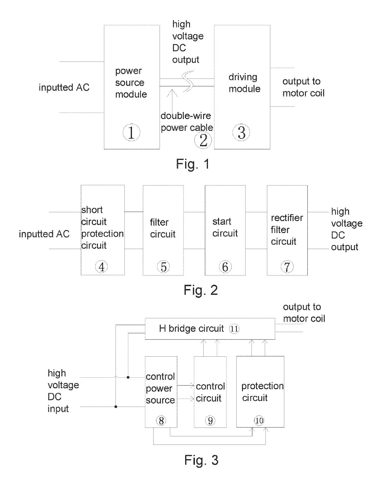
[0017]Referring to FIGS. 1-3, the present invention provides a power source device of an electric tool, comprising:

[0018]a power source module 1, comprising a short circuit protection circuit 4, a filter circuit 5, a start circuit 6 and a rectifier filter circuit 7, wherein the power source module 1 converts an inputted AC (alternating current) into a high voltage DC (direct current) through the short circuit protection circuit 4, the filter circuit 5, the start circuit 6 and the rectifier filter circuit 7;

[0019]a driving module 3, comprising an H bridge circuit 11, a control circuit 9, a protection circuit 10 and a control power source 8, wherein the driving module 3 divides the high voltage DC into a first DC and a second DC; the first DC is directly sent to the H bridge circuit 11 as a power source of a motor coil, and the H bridge circuit 11 outputs a voltage signal and a current signal for the motor coil according to a control signal; the second DC is sent to the control power ...


PUM


Abstract

A power source device of an electric tool includes: a power source module, including a short circuit protection circuit, a filter circuit, a start circuit and a rectifier filter circuit, wherein the power source module converts an inputted AC (alternating current) into a high voltage DC (direct current) through the short circuit protection circuit, the filter circuit, the start circuit and the rectifier filter circuit; a driving module, including an H bridge circuit, a control circuit, a protection circuit and a control power source, wherein the driving module divides the high voltage DC into a first DC and a second DC; and a power cable, respectively connected to the power source module and the driving module, for sending the high voltage DC from the power source module to the driving module.

Description

CROSS REFERENCE OF RELATED APPLICATION[0001]This is a U.S. National Stage under 35 U.S.C 371 of the International Application PCT / CN2015 / 088127, filed Aug. 26, 2015, which claims priority under 35 U.S.C. 119(a-d) to CN 201510411538.6, filed Jul. 14, 2015, and CN 201520508222.4, filed Jul. 14, 2015.BACKGROUND OF THE PRESENT INVENTIONField of Invention[0002]The present invention relates to a technical field of power sources of motors, and more particularly to a power source device of a brushless DC motor used by an electric tool.Description of Related Arts[0003]According to a circuit structure of a brushless DC motor, the brushless DC motor not only needs a high voltage DC power source for supplying motor coils, but also needs a control power source for supplying each control circuit. Only when the two kinds of power sources work at the same time, the motor is able to work normally. When using 220V AC as the power source of the motor, the 220V AC should be rectified and filtered so as...

Claims


Application Information

Patent Timeline
IPC IPC(8): H02M7/12B66D1/12H02M1/32
CPCH02M7/12B66D1/12H02M1/32H02M5/458H02M1/0006
Inventor WANG, KEWEIWEN, RUIGUANG
Owner HAMMER ELECTRIC POWER TOOLS
Why Eureka
Try Eureka