
Configuration method for control units

a technology of configuration method and control unit, applied in the direction of program control, program control, unauthorized memory use protection, etc., can solve the problems of only being able to perform the configuration work of trained staff, and the configuration work requires considerable time. , to achieve the effect of convenient and fast execution

Active Publication Date: 2013-10-08
BOMAG
View PDF12 Cites 0 Cited by
  • Summary
  • Abstract
  • Description
  • Claims
  • Application Information

AI Technical Summary

Benefits of technology

This method significantly reduces configuration time and eliminates the need for manual data re-entry, enabling faster and more convenient system startups, even in cases of reconfiguration, while ensuring data integrity through authentication and plausibility checks.

Problems solved by technology

This configuration work requires considerable time and can often only be performed by trained staff.

Method used


Image

  • Configuration method for control units
  • Configuration method for control units
  • Configuration method for control units

Examples


Embodiment Construction

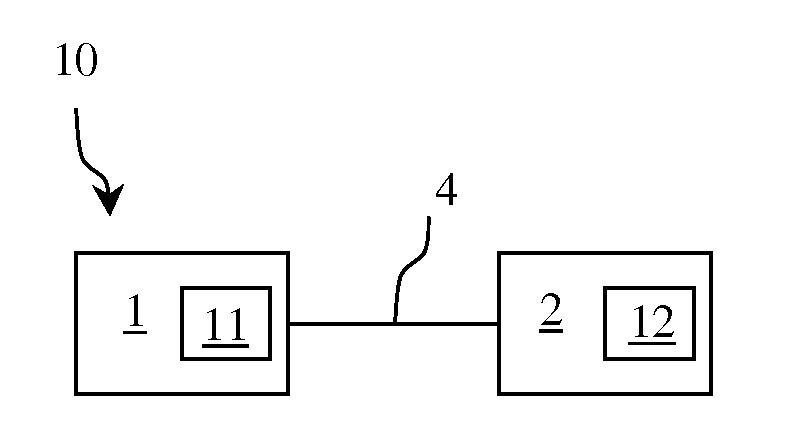
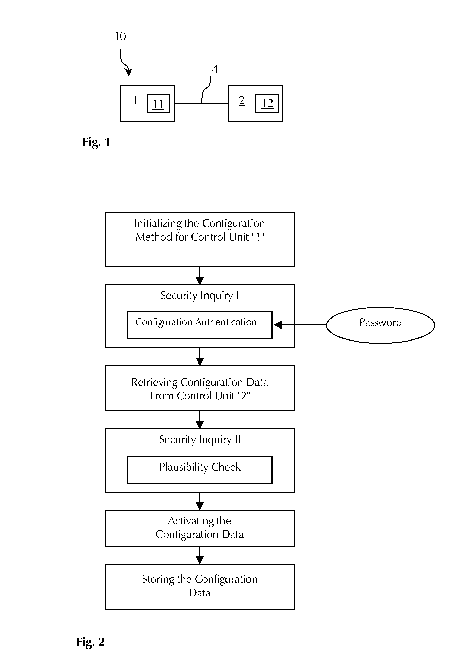
[0033]In FIG. 1 there is shown a machine control system 10 for a soil compaction roller with two control units 1 and 2 that are connected together by a CAN-bus 4. Either of the two control units 1 and 2 has an EEPROM data memory 11 and 12. The control unit 1 is mounted into the machine control system 10 and retrieves its configuration data from the already configured control unit 2 after it has been mounted in the machine control system 10. In this exemplary embodiment, the control unit 1 is a central control unit located on a higher hierarchy level. Meaning, control unit 1 is the master and control unit 2 the slave.

[0034]If in the machine control system 10 shown in FIG. 1 one of the two control units 1 or 2 is to be replaced because it is defective for example, the configuration of the newly mounted control unit can be carried out semi-automatically in accordance with the invention. FIG. 2 shows how the configuration method of the invention proceeds in case a replaced central contr...


PUM


Abstract

The invention relates to a configuration method for a control unit of a machine, the control unit having a data memory and being mounted in a machine control system having at least one already configured control unit with a data memory, the to-be-configured control unit communicating via a data connection with the already configured control unit of the machine control system and retrieving therefrom configuration data for its own configuration.

Description

CROSS-REFERENCE TO RELATED APPLICATIONS[0001]This application claims priority to German Patent Application No. 102005025645.7, filed Jun. 3, 2005, all of the disclosure of which is hereby incorporated by reference in its entirety.FIELD OF THE INVENTION[0002]The invention relates to a configuration method for a control unit of a machine, said control unit having a data memory and being mounted in a machine control system having at least one already configured control unit with a data memory.BACKGROUND OF THE INVENTION[0003]By such a configuration method, machine-specific data or parameters such as for example pump, valve, mechanical or software characteristics are transmitted as configuration data to the respective control units and stored in ROM, RAM or EEPROM data memories. Such a configuration method can be carried out after initial startup of a control unit for reconfiguration or initial configuration thereof or as a system startup configuration each time a machine control system...

Claims


Application Information

Patent Timeline
Patent Type & Authority Patents(United States)
IPC IPC(8): H04L9/32
CPCG05B19/042G05B19/0425G05B2219/24167G05B2219/25081
Inventor SCHOFL, MARTINFONDEL, CHRISTIANLAUX, ROBERT
Owner BOMAG
Learn More