Integrated vacuum gauge and regulator

a technology of vacuum gauge and regulator, which is applied in the direction of instruments, positive displacement liquid engines, specific gravity measurements, etc., can solve the problems of increasing the cost of the device, weakening the vacuum, and increasing the number of parts

Active Publication Date: 2013-10-15
DEVILBISS HEALTHCARE
View PDF14 Cites 4 Cited by
  • Summary
  • Abstract
  • Description
  • Claims
  • Application Information

AI Technical Summary

Benefits of technology

[0006]The present invention consists of a unitary, integrated regulator and gauge that provides ease of use for the user of the device, which connects to the device manifold at a single point, which exits the devices housing at a single point and which reduces the parts count, and therefore the cost, of the device.
[0008]The gauge is preferably concentrically aligned with the regulator, such that when the regulator is rotated, the gauge rotates with it. This gives the effect of the needle of the gauge being stationary, as with a magnetic compass, with the markings of the scale of the gauge moving thereunder, as the strength of the vacuum varies due to the rotation of the regulator.

Problems solved by technology

Regulation of the strength of the vacuum is typically controlled by regulating the amount of air that enters the manifold, and may be limited by the size or strength of the pump used to create the negative air pressure.
Allowing air to bleed into the manifold will tend to weaken the vacuum, while sealing the manifold or limiting the amount of air allowed to bleed into the manifold will generally strengthen the vacuum, to the limits of the pump.
This tends to complicate the design of the manifold and the device housing and increase the parts count for the device, thereby also increasing the cost of the device.

Method used


Image

  • Integrated vacuum gauge and regulator
  • Integrated vacuum gauge and regulator
  • Integrated vacuum gauge and regulator

Examples


Embodiment Construction

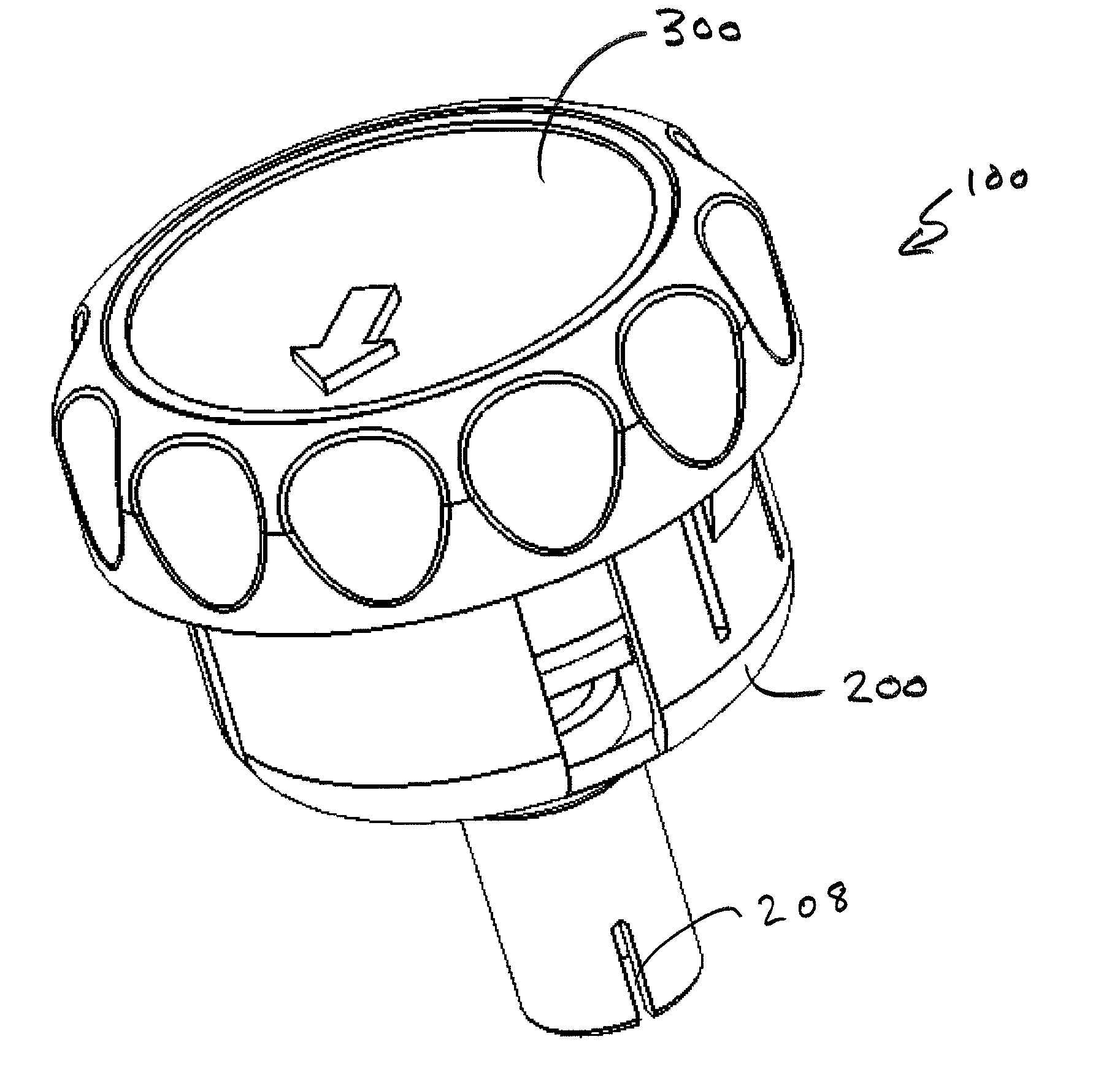
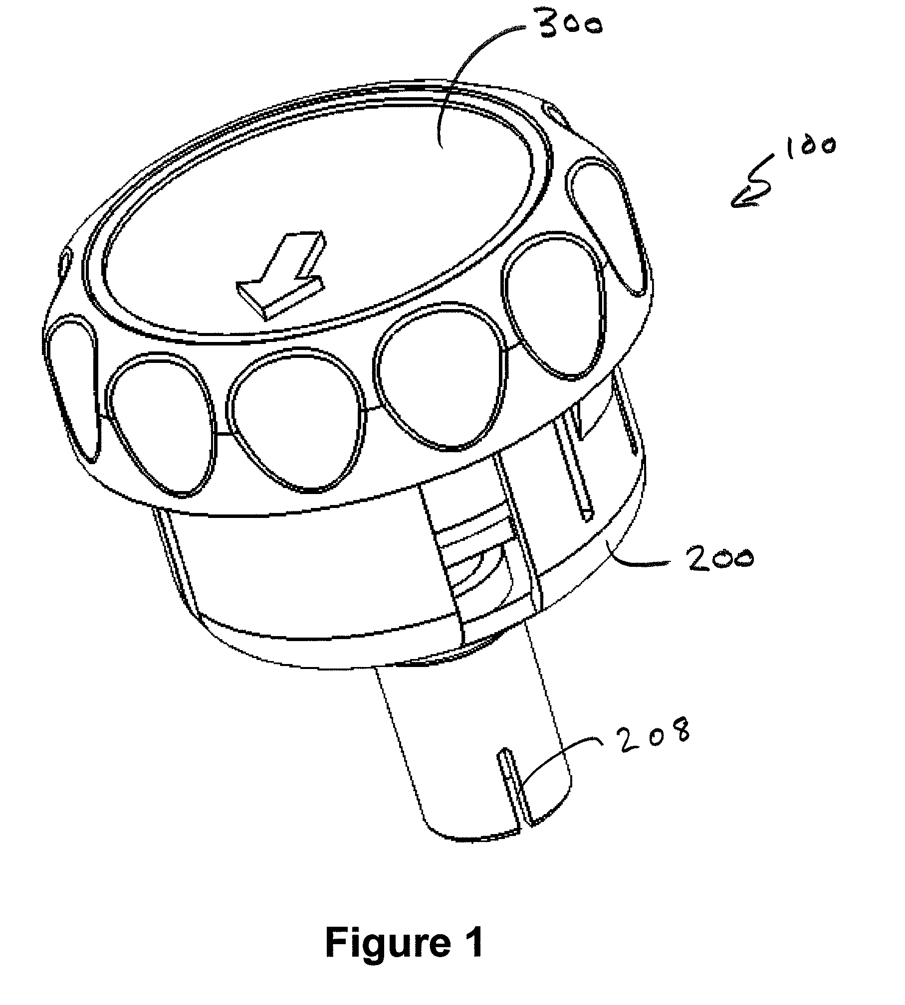
[0019]The device of the invention, shown essentially in FIG. 1, is intended to be integrated into the housing of devices requiring control of a vacuum, such as an aspirator or a surgical suction device. The assembly 100 device shown in FIG. 1 consists essentially of regulator 200 and vacuum gauge 300, oriented coaxially and fitted together, preferably with an interference fit, such that rotation of regulator 200 will also cause vacuum gauge 300 to rotate.

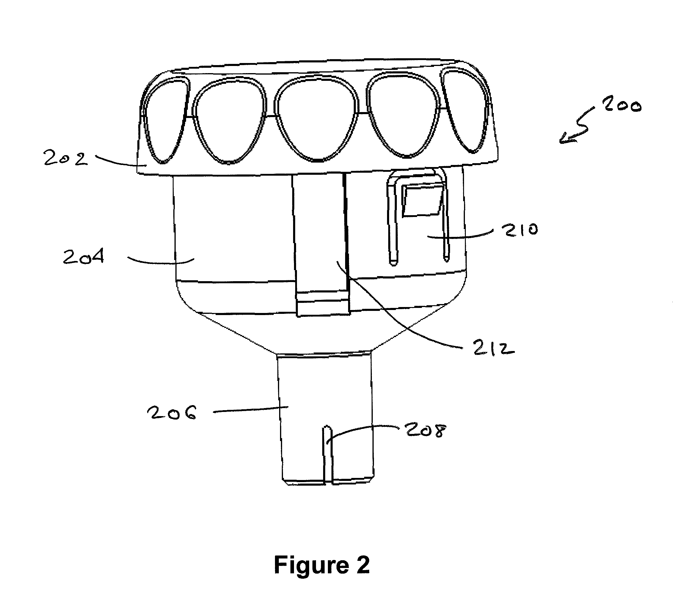
[0020]Regulator 200, shown in FIG. 2, consists of cylindrical body portion 204 which tapers to cylindrical boss portion 206. Boss portion 206 defines an opening 208 therein, the purpose of which will be discussed later. A beveled portion 202 is disposed at the top of cylindrical body 204 and may have integrated finger depressions defined thereon to assist a user in rotating regulator / gauge assembly 100.

[0021]The vacuum gauge 300 consists essentially of commercially available off the shelf vacuum gauge having the proper scale. The bo...


PUM

PropertyMeasurementUnit
diameteraaaaaaaaaa
rotationaaaaaaaaaa
shapeaaaaaaaaaa

Abstract

An integral regulator and gauge for a vacuum device consists of a circular regulator having the vacuum gauge inside thereof such that the regulator and gauge rotate about a common radial axis. An opening defined in a boss extending from the bottom of the regulator engages a sloped shoulder defined on the inside surface of a circular port in which the regulator is disposed, varying the size of an opening which allows air to bleed into the vacuum chamber to regulate the strength of the vacuum.

Description

FIELD OF THE INVENTION[0001]The present invention is directed to the field of devices providing and regulating vacuum, and, in particular, to such devices for use in medical appellations.BACKGROUND OF THE INVENTION[0002]Devices generating and utilizing a vacuum are well known in the art. For medical applications, such devices may be used, for example, to provide surgical suction for extracting liquids or semi-liquids from the body during surgery or dentistry, or for aspirators used for clearing the airway, mouth, and nasal passages of persons having chronic airway management issues, or, in the case of emergency, medical aspirators used to clear the airways of traumatized persons[0003]Such devices generally consist of a pump for providing negative air pressure connected to a manifold which may also connect a regulator and a vacuum gauge, and a tool for utilizing the vacuum. The regulator allows the regulation and setting of the strength of the vacuum, which, for medical applications ...

Claims


Application Information

Patent Timeline
Patent Type & Authority Patents(United States)
IPC IPC(8): G01L7/00
CPCA61M1/80
Inventor NEATROUR, JOEL DAVID
Owner DEVILBISS HEALTHCARE
Why Eureka
Try Eureka