Fluid filled type vibration damping device

a technology of vibration damping device and fluid filling, which is applied in the direction of shock absorbers, machine supports, mechanical equipment, etc., can solve the problems of reducing the amount of fluid flow through the orifice passage, causing vibration or noise, and affecting the effect of vibration or noise inhibition and rapid short circui

Active Publication Date: 2013-10-15
SUMITOMO RIKO CO LTD
View PDF37 Cites 13 Cited by
  • Summary
  • Abstract
  • Description
  • Claims
  • Application Information

AI Technical Summary

Benefits of technology

[0043]According to the present invention, the non-linearizing member is provided to endow non-linear elastic characteristics on the elastic deformation zone of the obstructing rubber elastic plate, so that the device is able to exhibit respective vibration damping effects with respect to vibrations in a multiple frequency ranges, while inhibiting impact or noise upon input of excessive vibration. Moreover, the obstructed space formed between the superposed surfaces between the partition member and the obstructing rubber elastic plate as well as the elastic deformation limiting member provided on the elastic deformation zone of the obstructing rubber elastic plate will provide further rapid short-circuit to the pressure receiving chamber and the equilibrium chamber.

Problems solved by technology

Additionally, in recent years, an application such as an automotive engine mount has a problem of occurrence of vibration or noise during input of excessive vibration load or jarring load.
It is conceivable that water hammer pressure accompanying bursts of the bubbles will be propagated through the first mounting member and the second mounting member and transmitted to components such as the car body that make up a vibration transmission system, producing noise or vibration which can be a problem.
There is a consequent risk that the amount of fluid flow through the orifice passage will decrease, making it difficult to achieve sufficient vibration damping effect against low-frequency, large-amplitude vibration exhibited by the orifice passage.
However, this arrangement poses a problem that pressure fluctuations in the pressure receiving chamber may not be reduced during input of high-frequency, small-amplitude vibration such as driving rumble, causing deterioration of vibration damping ability against high-frequency, small-amplitude vibration.
That is, in some instances, the fluid filled type vibration damping device disclosed in Patent Citation 1 cannot be sufficient to meet the requirements of achieving both of (i) vibration damping effect against low-frequency, large-amplitude vibration exhibited by the orifice passage and (ii) vibration damping effect against high-frequency, small-amplitude vibration exhibited by elastic deformation of the obstructing rubber elastic plate, and further achieving (iii) inhibition of impact or noise caused by pressure fluctuations in the pressure receiving chamber in association with input of excessive vibration.

Method used


Image

  • Fluid filled type vibration damping device
  • Fluid filled type vibration damping device
  • Fluid filled type vibration damping device

Examples


first embodiment

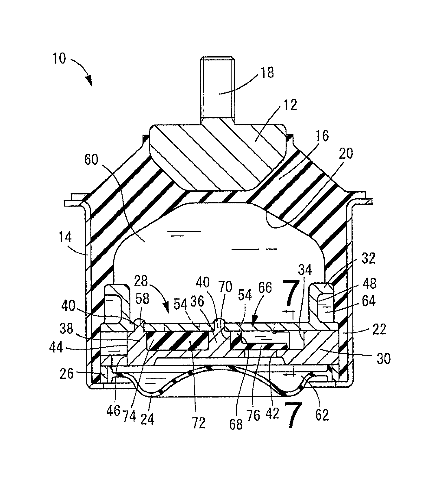
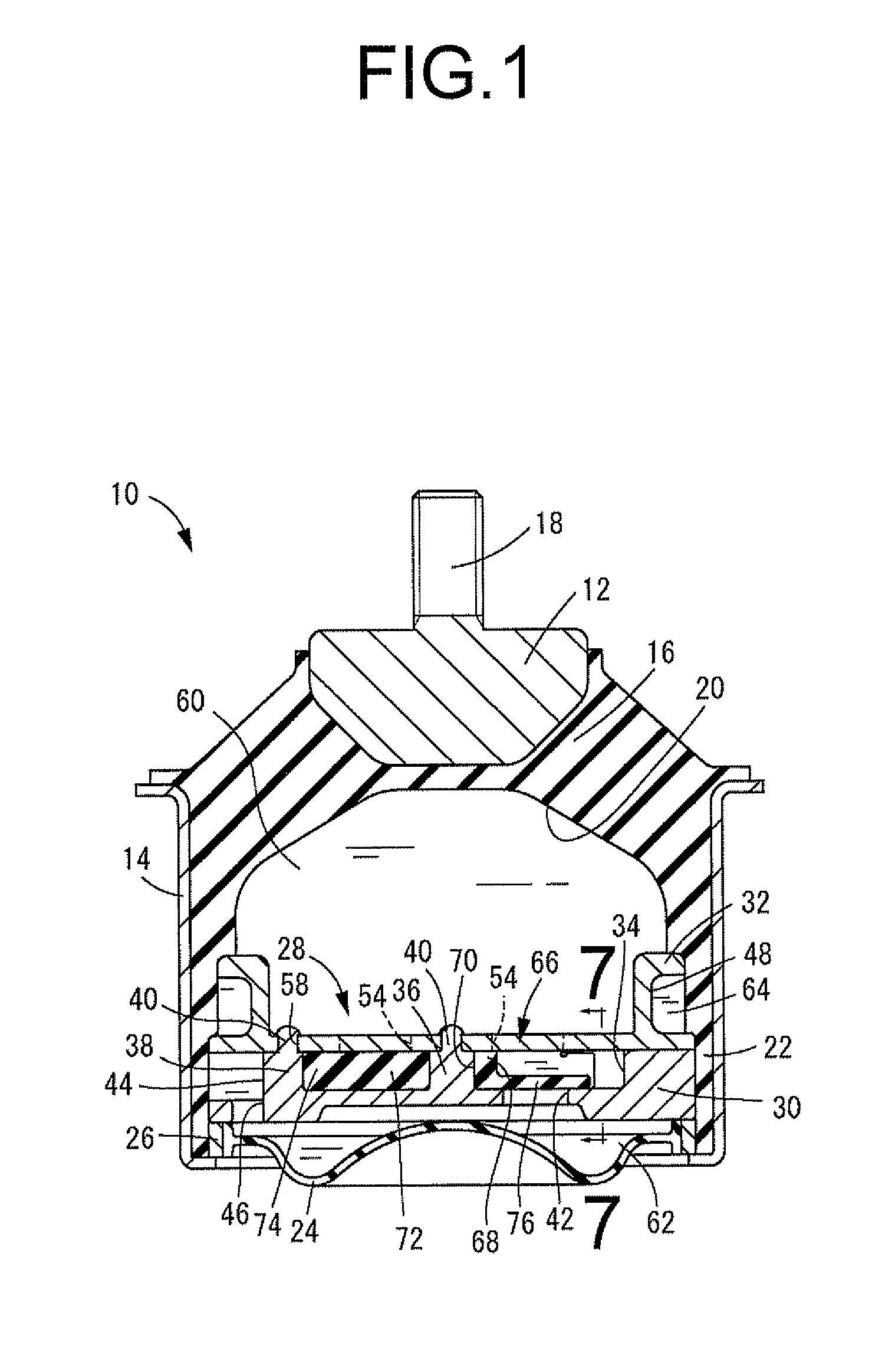
[0099]A more specific understanding of the invention will be provided through the following detailed description of the embodiments of the present invention, made with reference to the accompanying drawings. Referring first to FIG. 1, there is depicted an automotive engine mount 10 as the fluid filled type vibration damping device according to the present invention. The automotive engine mount 10 has a construction in which a first mounting member 12 of metal and a second mounting member 14 of metal are connected to each other by a main rubber elastic body 16. The first mounting member 12 is mounted onto the power unit of the automobile, while the second mounting member 14 is mounted onto the vehicle body, thereby providing vibration damped linkage of the power unit and the vehicle body via the engine mount 10.

[0100]Whereas FIG. 1 depicts the automotive engine mount 10 in isolation prior to installation in a vehicle, with the engine mount 10 installed in the vehicle, distributed loa...

second embodiment

[0128]Specifically, referring to FIGS. 9 and 10, there is depicted an obstructing rubber elastic plate 84 employed in an automotive engine mount as a second embodiment according to the present invention. Each of elastic valve portions 76 has abutting projections 86 serving as opposing contact projections that are integrally formed with the outer peripheral edge of the elastic valve portions 76. These abutting projections 86, 86 are integrally formed with the elastic valve portion 76 and project upwardly, being circumferentially spaced apart from one another as well as being circumferentially spaced apart from each circumferential end of the circumference retaining portion 74. The height dimension of the abutting projection 86 is made smaller than that of the circumference retaining portion 74. Accordingly, in the state where the obstructing rubber elastic plate 84 is superposed against the partition member 30, the abutting projection 86 is positioned spaced apart from the pressure r...

third embodiment

[0130]It should be noted that no particular limitation is imposed as to the shape, size, construction, number, placement and other aspects of the abutting projection 86. For example, as depicted in FIGS. 11 and 12, an obstructing rubber elastic plate 88 employed in an automotive engine mount as a third embodiment according to the present invention would also be acceptable. The obstructing rubber elastic plate 88 has a structure in which a single abutting projection 86 is provided to a circumferentially center section of the outer peripheral edge of the each elastic valve portion 76.


PUM


Abstract

A fluid filled type vibration damping device including: an obstructing rubber elastic plate disposed so as to obstruct a communication aperture that connects a pressure receiving chamber and an equilibrium chamber; contact retaining portions arranged on an outer peripheral edge of the rubber plate and held in contact against a partition member; an elastic deformation zone arranged circumferentially between the contact retaining portions of the rubber plate so as to undergo elastic deformation on a basis of pressure differential between the pressure receiving chamber and the equilibrium chamber to be spaced away from the partition member to cause the aperture to open up; and a non-linearizing member provided such that the elastic characteristics of the elastic deformation zone become more rigid in a non-linear manner in association with increase in an amount of its deformation.

Description

TECHNICAL FIELD[0001]The present invention relates to a fluid filled type vibration damping device adapted to utilize vibration damping effect based on the flow action of a non-compressible fluid sealed therein.BACKGROUND ART[0002]Vibration damping devices such as vibration damping linkages or vibration damping supports have been used to be interposed between components that make up a vibration transmission system. One type of known device is a vibration damping device having a first mounting member and a second mounting member linked by a main rubber elastic body, and a fluid filled type vibration damping device is a developed type thereof. This fluid filled type vibration damping device includes a pressure receiving chamber whose wall is partially defined by a main rubber elastic body; and an equilibrium chamber whose wall is partially defined by a flexible film, the two chambers being filled with a non-compressible fluid, and the two chambers communicating with each other through...

Claims


Application Information

Patent Timeline
Patent Type & Authority Patents(United States)
IPC IPC(8): F16F5/00
CPCF16F13/106
Inventor OKUMURA, KEIKOMIYA, YASUHIRO
Owner SUMITOMO RIKO CO LTD
Why Eureka
Try Eureka