Deployable optical fiber cartridge

a technology of optical fiber and cartridge, which is applied in the field of spool, can solve the problems of optical fiber becoming loose on the spool, causing tension and possibly breaking of optical fiber, and causing fiber to breakage, so as to prevent fiber tension and optical fiber breakage

Active Publication Date: 2013-10-15
GENERAL DYNAMICS MISSION SYST INC
View PDF8 Cites 8 Cited by
  • Summary
  • Abstract
  • Description
  • Claims
  • Application Information

AI Technical Summary

Benefits of technology

[0003]An optical fiber is stored on a spool having a cylindrical portion and a compressible member over the cylindrical portion. The compressible member is not affected by ambient water pressure. Thus, when the spool is submerged, the water will saturate the compressible member and the water pressure will not cause the compressible member to collapse. When the optical fiber is wound on the spool, the tension will cause the compressible member to be slightly compressed. This cushioning prevents excess tension from being applied to the optical fiber. In an embodiment, the compressible member is an open cell foam. When the spool is submerged the water fills the cells and the open cell foam will not collapse under pressure. In other embodiments, the compressible member can include a mechanical spring. When submerged, the water will fill the spaces between the spring and the spool. The springs will not be compressed by the water pressure. In order to improve the movement of water into the compressible member, the spool may have holes or openings.
[0005]The spool of optical fiber may be placed on a remotely operated vehicle (ROV). As the ROV moves through the water, a feed system will pull the optical fiber from the spool at a rate that is approximately equal to or faster than the movement of the ROV. By emitting the optical fiber from the ROV, the optical fiber is essentially stationary in the water and there is no tension applied to the fiber. If the optical fiber becomes tangled, it will not go through the feed system and the movement of the ROV can create tension and possibly breakage of the optical fiber. In another embodiment, a second spool of optical fiber can be mounted in a surface structure on or adjacent to a surface support ship. A second feed system can be coupled to the second optical fiber spool. If the ship moves, the optical fiber can be released from the second spool to prevent tension in the fiber.

Problems solved by technology

If the compressible member of the spool was made of a closed cell foam, the pressure would eventually cause the compressible member to collapse.
This would cause the optical fiber to become loose on the spool and potentially tangled.
If the optical fiber becomes tangled, it will not go through the feed system and the movement of the ROV can create tension and possibly breakage of the optical fiber.

Method used


Image

  • Deployable optical fiber cartridge
  • Deployable optical fiber cartridge
  • Deployable optical fiber cartridge

Examples


Embodiment Construction

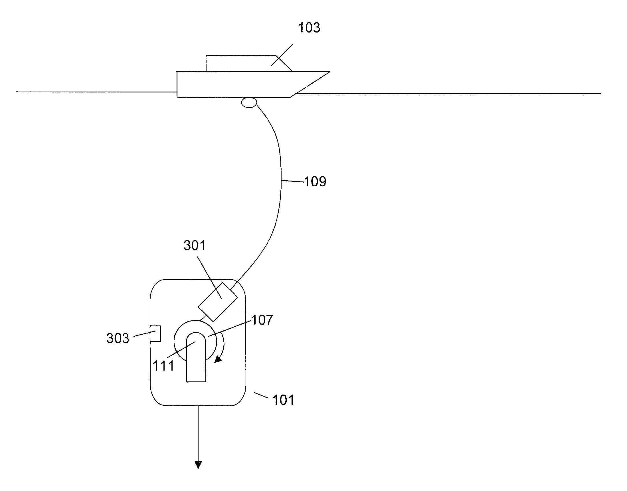
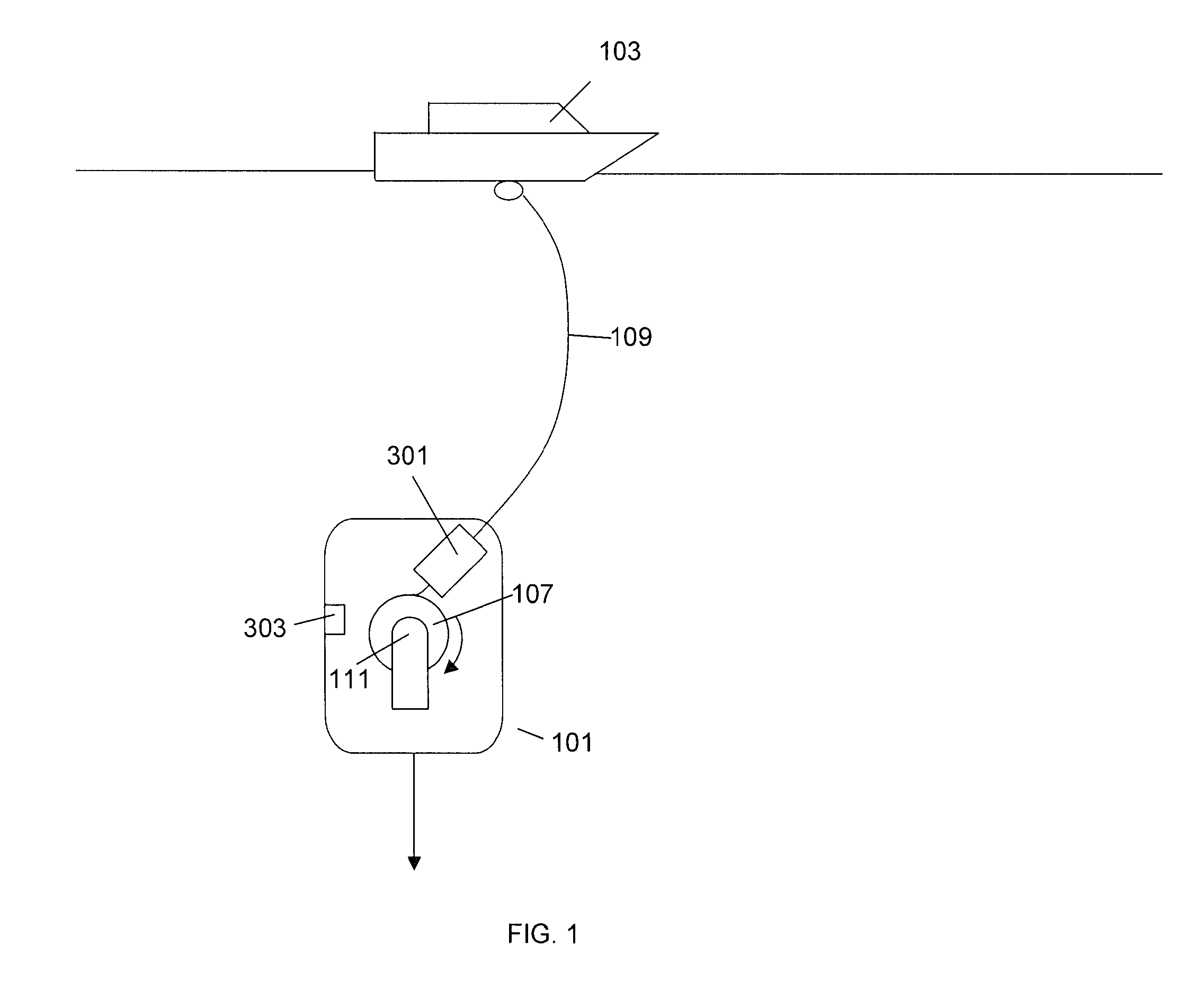
[0019]The present invention is directed towards a spool for storing a fiber for underwater applications. With reference to FIG. 1, in an embodiment, the fiber can be an optical fiber 109 that is stored on a spool 107 that is used for communications between a support ship 103 and a Remotely Operated Vehicle (ROV) 101. An end of the optical fiber 109 can be coupled to communications equipment on the support ship 103 and the other end of the optical fiber 109 can be coupled to communications and control equipment on the ROV 101.

[0020]The spool 107 of the optical fiber 109 is stored on the ROV 101. As the ROV 101 travels, the spool 107 can rotate which causes the optical fiber 109 to stream out of the ROV 101. The end of the optical fiber 109 can be coupled to a rotating coupling 111 so the spool 107 can rotate freely. In an embodiment, a sensor can detect the relative velocity of the ROV 101 through the water and then control the rotational rate of the spool 107 to emit the optical fib...


PUM


Abstract

A spool has a cylinder, a first flange coupled to a first end of the cylinder and a second flange coupled to a second end of the cylinder. A compressible material surrounds the cylinder and an optical fiber is wrapped around the compressible material. When tension is applied to the optical fiber the compressible material can be deformed to reduce the tension on the optical fiber. When submerged underwater the water pressure will not compress the compressible material.

Description

FIELD OF INVENTION[0001]The application is directed towards a spool that can be used for storing a fiber in underwater applications.BACKGROUND[0002]Fibers such as optical fibers have been used in underwater applications to transmit and receive information. For example, an underwater device can have a propulsion system and a direction control mechanism. The underwater device can be deployed by a support ship and an optical fiber can be coupled between the underwater device and the support ship. The support ship can transmit control information to the underwater device that is used to operate the direction control mechanism.SUMMARY OF THE INVENTION[0003]An optical fiber is stored on a spool having a cylindrical portion and a compressible member over the cylindrical portion. The compressible member is not affected by ambient water pressure. Thus, when the spool is submerged, the water will saturate the compressible member and the water pressure will not cause the compressible member to...

Claims


Application Information

Patent Timeline
Patent Type & Authority Patents(United States)
IPC IPC(8): F16L1/12
CPCB65H75/14B65H75/425B65H2701/514B65H2701/32
Inventor HAWKES, GRAHAMEPSTEIN, JONATHAN
Owner GENERAL DYNAMICS MISSION SYST INC
Why Eureka
Try Eureka