
Automatic transmission

a transmission and automatic technology, applied in the direction of gearing details, gearing, transportation and packaging, etc., can solve the problems of deterioration in noise and vibration, noise and vibration tend to be generated by the output gear, and the transmission is enlarged

Active Publication Date: 2013-10-15
JATCO LTD
View PDF9 Cites 0 Cited by
  • Summary
  • Abstract
  • Description
  • Claims
  • Application Information

AI Technical Summary

Benefits of technology

[0030]a first drum supporting the second friction element on an inner circumferential side thereof, the first drum supporting the first friction element on an outer circumferential side thereof such that the first friction element is overlapped with the second friction element in a radial direction of the input member, the first drum being connected to the input member,
[0009]The present invention has been made in view of the above problems. It is an object of the present invention to provide an automatic transmission that is capable of enhancing NV performance of an output member and suppressing upsizing of a control valve body and a common carrier to thereby reduce costs thereof.

Problems solved by technology

However, in the automatic transmission as shown in FIG. 9B of the above conventional art, the following problems are caused due to a layout of the components used.(1) Deterioration in Noise and Vibration Performance (NV Performance) of an Output Gear:
As a result, noise and vibration tend to be generated from the output gear.
Further, in the layout in which the hub member of brake B1 is disposed on the inner circumferential side of the output gear, if it is intended to directly support the output gear by the transmission case, an intermediate wall for supporting the output gear must be provided to thereby cause upsizing of the transmission and an increase in cost.(2) Upsizing of a Control Valve Body and Increase in Cost:
For this reason, upsizing of the control valve body is caused, thereby resulting in an increase in cost.(3) Upsizing of a Common Carrier and Increase in Cost:
For this reason, upsizing of the common carrier is caused, thereby resulting in an increase in cost.

Method used


Image

  • Automatic transmission
  • Automatic transmission
  • Automatic transmission

Examples


Embodiment Construction

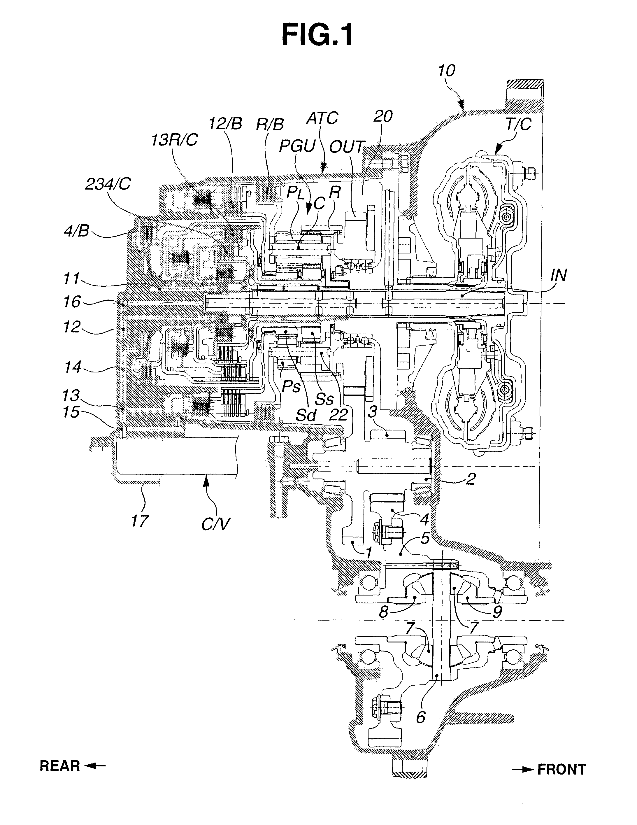
[0047]Referring to FIGS. 1-11, an automatic transmission according to an embodiment of the present invention is explained. In this embodiment, the automatic transmission is applied to a front-engine front-wheel-drive engine vehicle (a FF engine vehicle) which has a parallel arrangement of an input shaft and an output shaft.

[0048]First, a construction of the automatic transmission according to the embodiment is explained. The construction includes “general construction”, “speed change construction” and “arrangement of respective elements within a transmission chamber”.

[0049][General Construction]

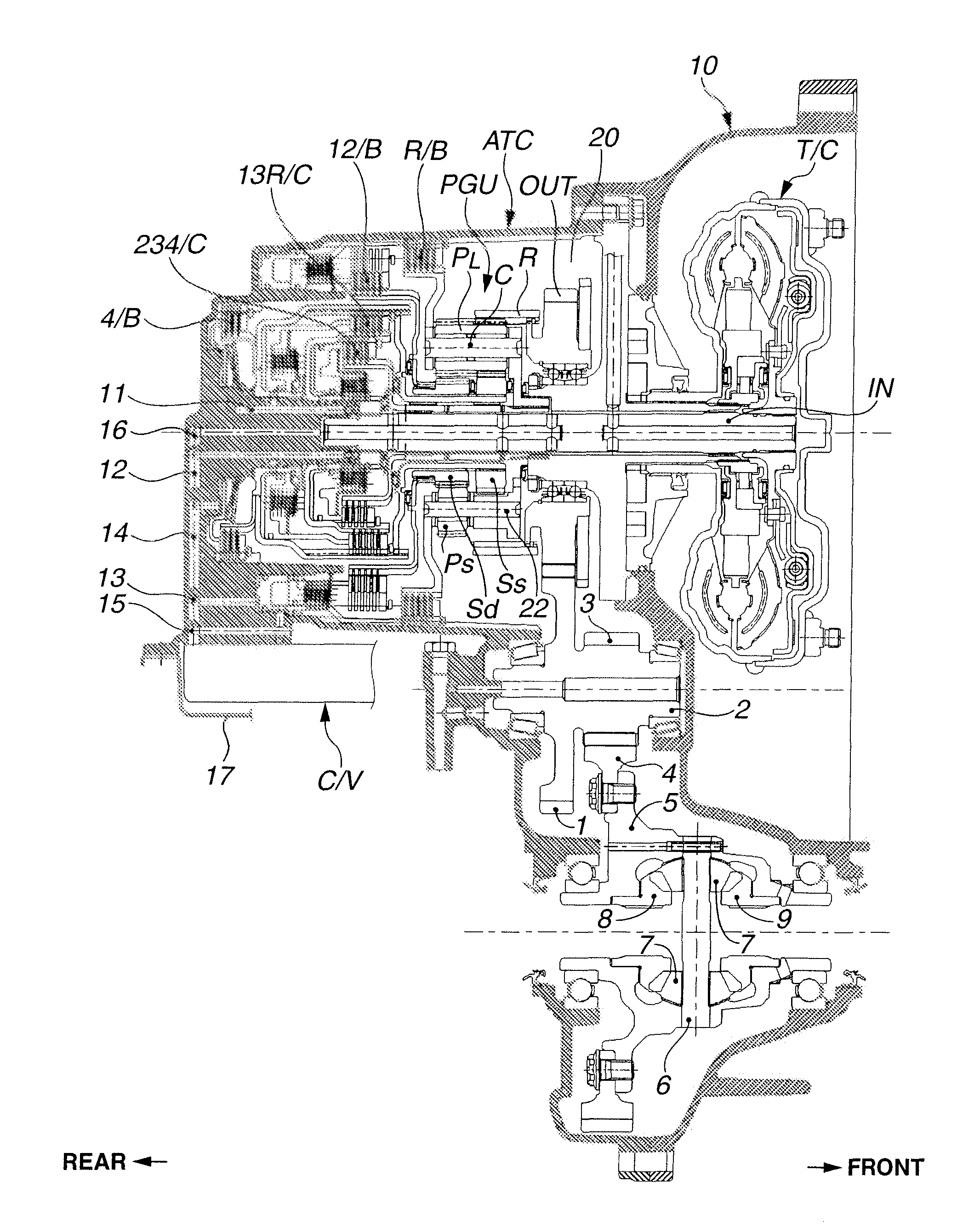
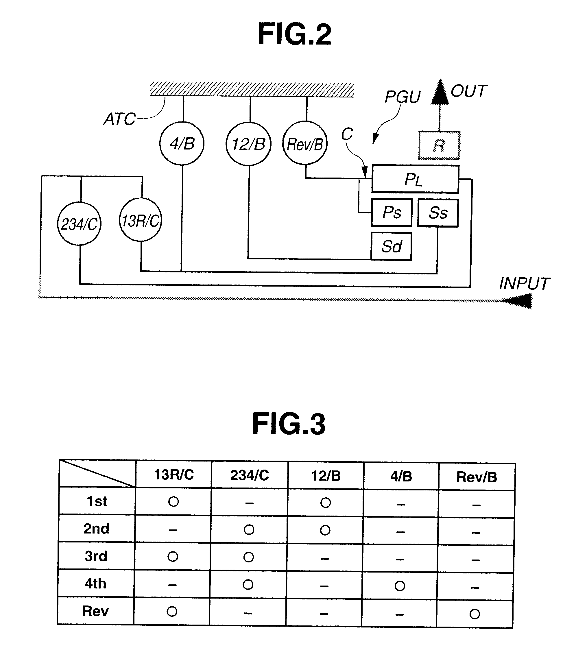
[0050]FIG. 1 is a vertical cross section of the automatic transmission according to the embodiment, showing the general construction thereof. FIG. 2 is a skeleton diagram showing the automatic transmission according to the embodiment. Referring to FIG. 1 and FIG. 2, a construction of planetary gearsets and a construction of friction elements in the automatic transmission are explained.

[0051]A...


PUM


Abstract

An automatic transmission including a Ravigneaux planetary gear unit, an input member, an output member disposed on one side of the Ravigneaux planetary gear unit, five friction elements disposed on the other side of the Ravigneaux planetary gear unit, and a partition member cooperating with an automatic transmission case to define a transmission chamber in which the output member, the Ravigneaux planetary gear unit, and the respective friction elements are accommodated. The output member is supported on a cylindrical portion extending from the partition member toward the Ravigneaux planetary gear unit in an axial direction of the input member.

Description

BACKGROUND OF THE INVENTION[0001]The present invention relates to an automatic transmission which can realize four forward speeds and one reverse speed by combination of engagement and disengagement of five friction elements through a Ravigneaux planetary gear unit.[0002]There has been proposed an automatic transmission that realizes four forward speeds and one reverse speed by combination of engagement and disengagement of two clutches and three brakes through a Ravigneaux planetary gear unit (a composite planetary gearset composed of two planetary gearsets). Japanese Patent Application Unexamined Publication No. 10-169730 discloses such an automatic transmission in FIG. 9A and FIG. 9B.[0003]However, in the automatic transmission as shown in FIG. 9B of the above conventional art, the following problems are caused due to a layout of the components used.[0004](1) Deterioration in Noise and Vibration Performance (NV Performance) of an Output Gear:Brake B1 is disposed on an inner circu...

Claims


Application Information

Patent Timeline
Patent Type & Authority Patents(United States)
IPC IPC(8): F16H3/44
CPCF16H3/663F16H2003/445F16H2200/0043F16H2200/2005F16H2200/2023F16H2200/2043F16H3/62F16H57/023
Inventor OGURI, KAZUOWATANABE, KENICHIURUSHIBATA, TAKAYOSHI
Owner JATCO LTD
Learn More