Adjustable star wheel

a technology of star wheel and wheel, which is applied in the direction of conveyors, furnaces, light and heating equipment, etc., can solve the problems of unoptimized shape of the structure defining the pocket, and achieve the effect of convenient and quick methods

Active Publication Date: 2013-10-22
ZEPF TECH UK
View PDF22 Cites 21 Cited by
  • Summary
  • Abstract
  • Description
  • Claims
  • Application Information

AI Technical Summary

Benefits of technology

[0014]Thus a simple star wheel is realised that may be readily adjusted between a first setting where larger containers may be conveyed using the larger pocket, and a second setting where smaller containers may be conveyed using the smaller pocket. Furthermore, the present invention employs a different approach to that commonly found in conventional adjustable star wheels. In the past, adjustable star wheels use a common structural member to define a pocket for various sized containers. This may be one or more fingers that rotate to define a pocket of varying size (like EP-A-0,355,971) or jaws having a shape that is so general as to fit a range of container sizes (like EP-A-0,412,059). In both cases, the shape of the structure defining the pocket is not optimal for any particular container, but instead represents a compromise that will work adequately with a number of container sizes.
[0016]Such an arrangement is advantageous because it allows the shape and size of the larger pocket and / or the smaller pocket to be tailored to exactly the container they are to receive. As a result, more than two points of support may be provided or an extended line of contact may be provided. Hence, a bespoke pocket may arise that meets the needs of a container exactly. For example, the shape of the pocket may correspond to that of the part of the container supported by the pocket. Alternatively, the pocket may be shaped to be close to that of the container, but may include portions that leave a little clearance such that the container may rotate slightly as it is received within the pocket and as it is released from the pocket. In fact, the pockets may be shaped to assist these feed in and hand off processes.
[0021]Optionally, the star wheel may comprise a cladding plate attached to the pocket-defining disc and arranged such that at least part of the jaws are sandwiched between the pocket-defining disc and the cladding plate. Such an arrangement helps to retain the jaws in position. Preferably, all of the jaws are sandwiched between the pocket-defining disc and the cladding plate when the jaws are in the retracted position. With this arrangement, the cladding plate may be provided with a corresponding shape to the peripheral portion of the pocket-defining disc, such that the larger pocket is defined by both the cladding plate and the pocket-defining disc. For example, the top of the larger pocket may be defined by the cladding plate and the bottom of the larger pocket may be defined by the pocket-defining disc. Then, the smaller pocket is defined by the jaws that extend from between the cladding plate and the pocket-defining disc.
[0027]In this way, only a single operation is required to convert all the pockets in the star wheel between the larger and smaller positions. Hence, a star wheel is provided that very quickly converts from conveying a plurality of larger containers to a plurality of smaller containers.
[0032]It will be appreciated that combinations of the features described above results in a star wheel that provides an easy and quick method of converting between larger and smaller containers. No spare parts are required and the star wheel need not be removed. Change of containers on a handling line merely requires a single rapid adjustment of each star wheel from one preset position to the other.

Problems solved by technology

In both cases, the shape of the structure defining the pocket is not optimal for any particular container, but instead represents a compromise that will work adequately with a number of container sizes.

Method used


Image

  • Adjustable star wheel
  • Adjustable star wheel
  • Adjustable star wheel

Examples


Embodiment Construction

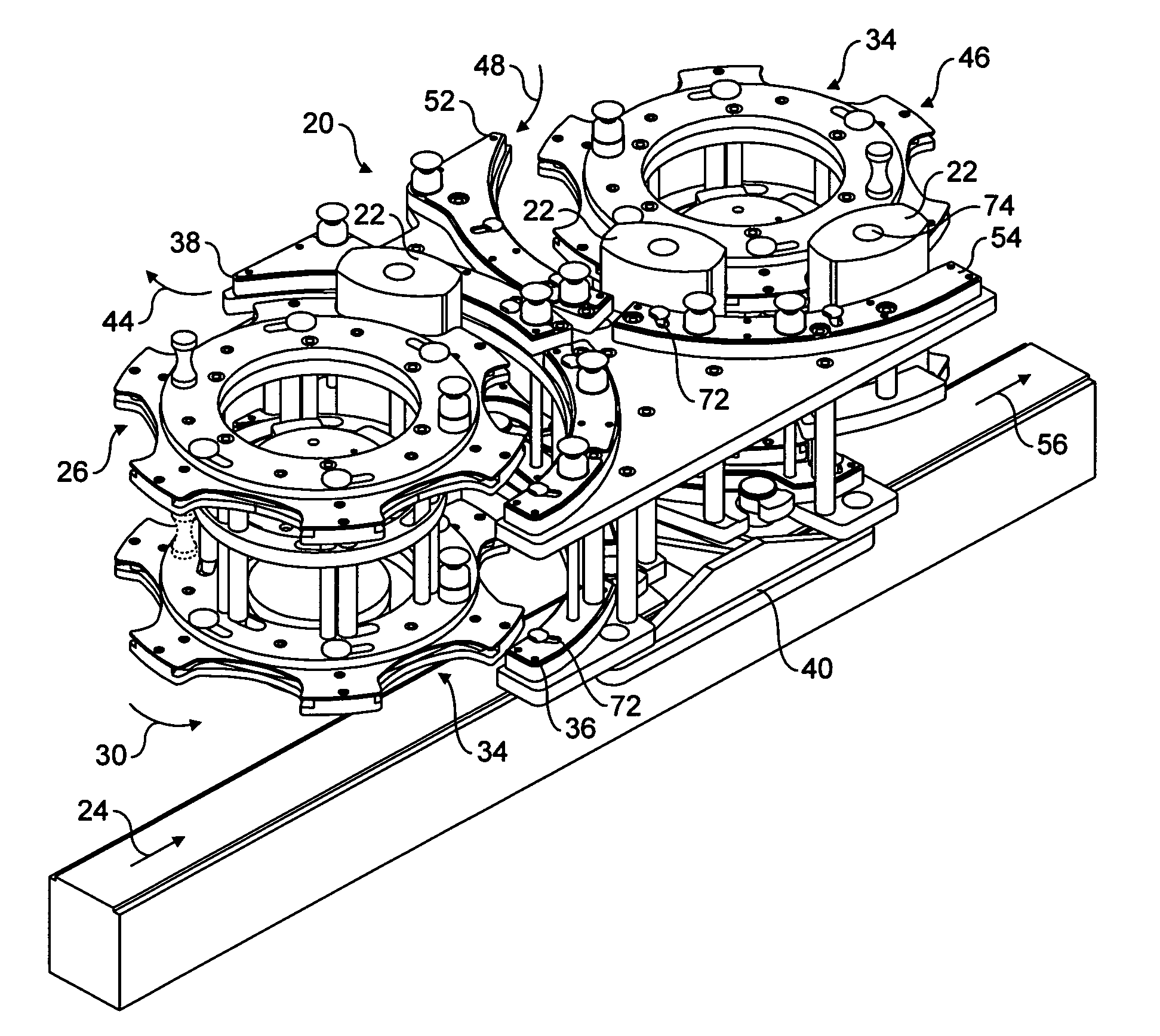
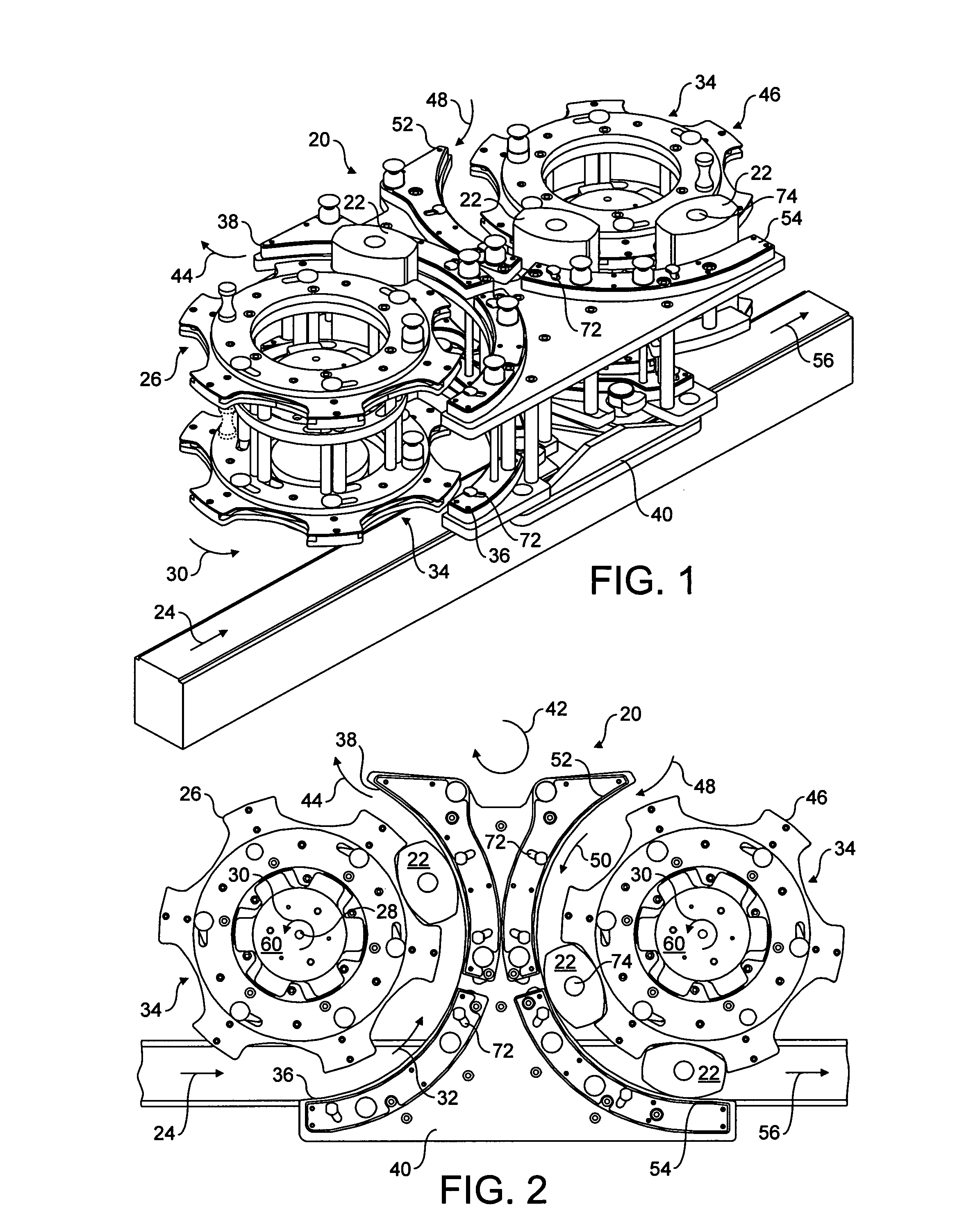
[0046]A conveyor assembly 20 is shown in perspective in FIG. 1 and in plan in FIG. 2. The conveyor assembly 20 is used to divert containers 22 from a rectilinear path and feed the containers 22 into a rotary machine (not shown) for processing such as filling or labelling. The conveyor assembly 20 then takes processed containers 22 from the rotary machine and passes them back onto the rectilinear path.

[0047]The conveyor assembly 20 first takes containers 22 arriving along a linear input path denoted by arrow 24. A first star wheel 26 rotates about a central axis 28 as shown at 30 so as to convey containers 22 along the path shown at 32. Containers 22 are received within pockets 34 defined around the periphery of star wheel 26. The containers 22 are then urged along the path 32 as constrained by the combination of the pockets 34 and guide rails 36 and 38 provided on a guide rail assembly 40.

[0048]The containers 22 are released at a hand off position where they are received by a rotary...


PUM


Abstract

The present invention provides an adjustable star wheel provided with at least one interchangeable pocket for receiving a container to be conveyed. The star wheel comprises a larger pocket of fixed shape and size, moveable jaws defining a smaller pocket having a fixed shape and size, an actuator disc rotatable about the central axis, and a cam mechanism linking the jaws to the actuator disc to cause radial movement of the jaws. In an extended position, the jaws move the smaller pocket into coincidence with the larger pocket thereby configuring the star wheel to receive containers in the smaller pocket. In the retracted position, the jaws are clear of the larger pocket thereby configuring the star wheel to receive containers in the larger pocket.

Description

CROSS REFERENCE TO RELATED APPLICATIONS[0001]This application is a national stage application filed under 35 U.S.C. 371 of International Application No. PCT / GB2008 / 003250, filed Sep. 24, 2008, which claims priority from Great Britain Application No. 0718658.8, filed Sep. 24, 2007.FIELD OF THE INVENTION[0002]The present invention relates to an adjustable star wheel for use with containers being processed on an automated handling line.BACKGROUND TO THE INVENTION[0003]Star wheels are used on various types of automated handling lines to convey containers to and from, and within, various machines such as rotary packaging machines. In particular, star wheels are used to convey containers between rectilinear conveyors to a rotating machine part and back to a rectilinear conveyor. The star wheel may take a container from a conveyor such as screw feed and pass the container to a machine such as a washer, filler, capper or labeller. Sometimes, orientation of the container is important and the...

Claims


Application Information

Patent Timeline
Patent Type & Authority Patents(United States)
IPC IPC(8): B65G47/84
CPCB65G47/846B65G29/00
Inventor MCALLISTER, MARKSPENCE, IAN
Owner ZEPF TECH UK
Why Eureka
Try Eureka