Shield connector having a shield shell connected to a metallic case and a shield conductor

a shield connector and shield shell technology, applied in the direction of connection, electrical apparatus, coupling device connection, etc., can solve the problems of electrolytic corrosion, water cannot penetrate toward the shield conductor, etc., and achieve the effect of high strength and easy deformation

Inactive Publication Date: 2013-10-22
SUMITOMO WIRING SYST LTD
View PDF11 Cites 31 Cited by
  • Summary
  • Abstract
  • Description
  • Claims
  • Application Information

AI Technical Summary

Benefits of technology

[0009]The first seal member prevents water from penetrating into the housing through a clearance between the housing and the wire while the second seal member prevents water from penetrating into the inside of the shield shell through a clearance between the housing and the shield shell. Thus water cannot penetrate toward the shield conductor through the inside of the shield shell.
[0010]The shield conductor may be formed by electrically connecting a plurality of types of metals having different standard electrode potentials. Thus, the shield conductor may be formed by using a metal having high strength at a position where strength is required and using an easily deformable metal at a position where bending deformation is required. Electrolytic corrosion occurs if an electrolyte solution, such as moisture, is present in a part where different types of metals having different standard electrode potentials are connected. Thus, both metals are dissolved in the form of ions into water and corrosion progresses by an electrochemical reaction. However, the second seal member prevents water from penetrating through a clearance between the housing and the shield shell and into a part where different types of metals having different standard electrode potentials are connected. Thus, electrolytic corrosion is not likely to occur between different types of metals having different standard electrode potentials.

Problems solved by technology

Thus water cannot penetrate toward the shield conductor through the inside of the shield shell.
Electrolytic corrosion occurs if an electrolyte solution, such as moisture, is present in a part where different types of metals having different standard electrode potentials are connected.

Method used


Image

  • Shield connector having a shield shell connected to a metallic case and a shield conductor
  • Shield connector having a shield shell connected to a metallic case and a shield conductor
  • Shield connector having a shield shell connected to a metallic case and a shield conductor

Examples


Embodiment Construction

[0016]A shield connector in accordance with the invention is identified by the numeral 10 in FIG. 4 and is to be mounted in a mounting hole C1 in a metal case C that contains a device.

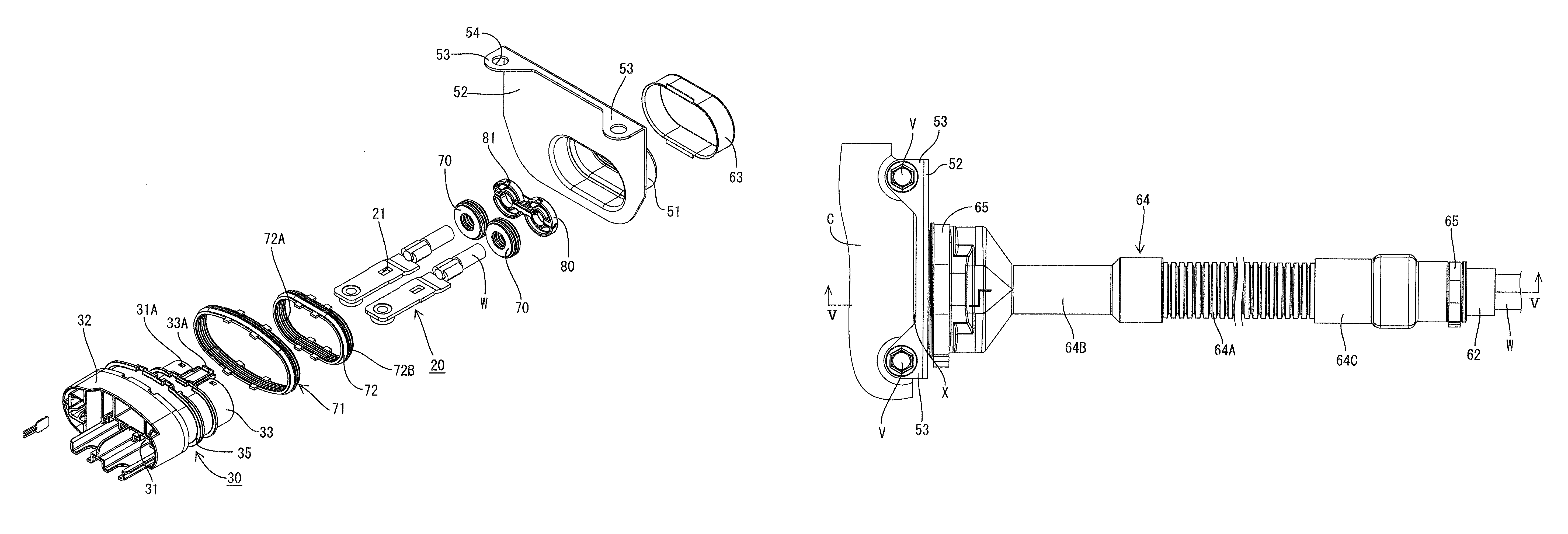
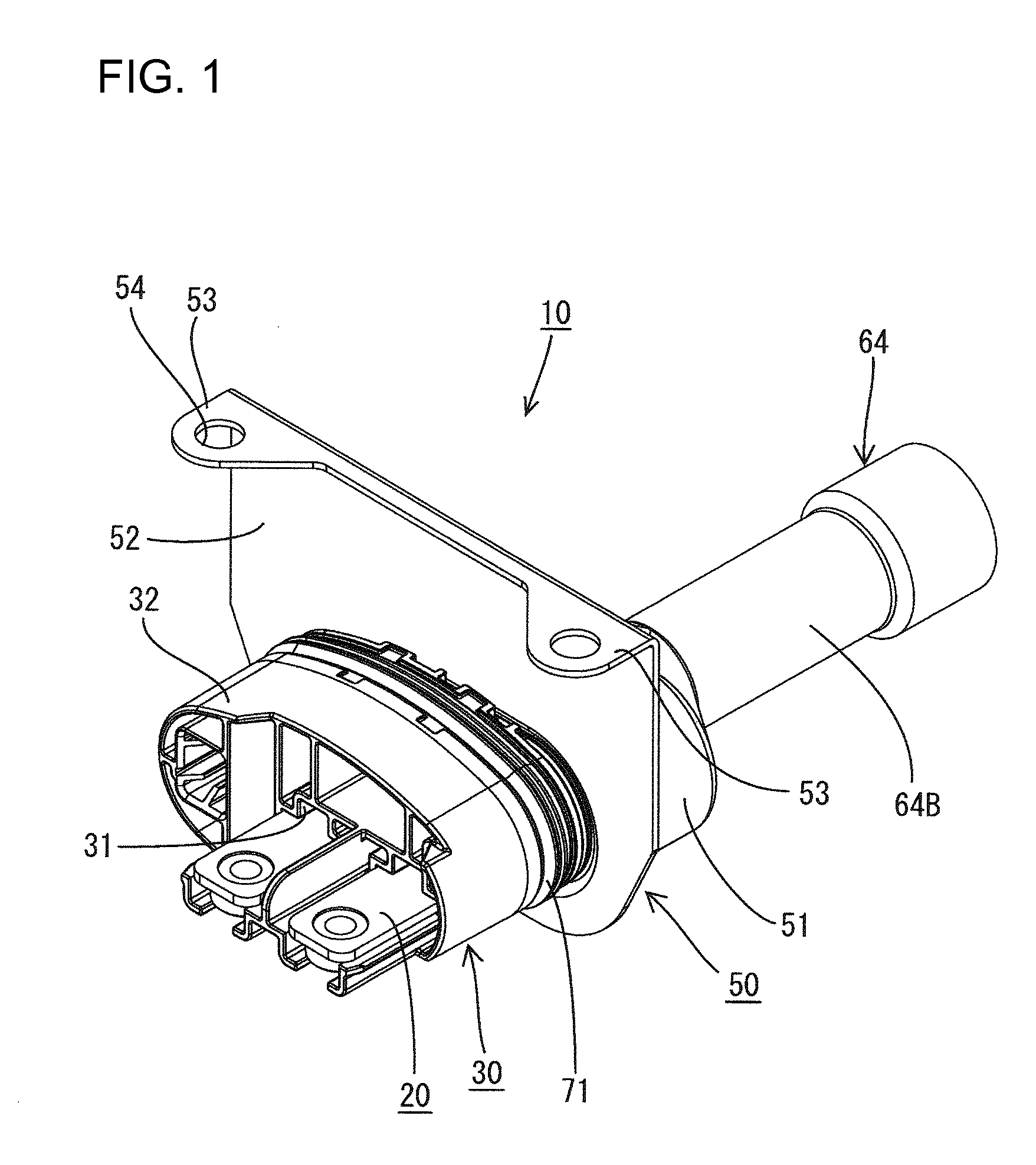
[0017]As shown in FIG. 1, the shield connector 10 includes a housing 30 made of synthetic resin. Terminal fittings 20 connected to ends of wires W are accommodated in the housing 30 and a shield shell 50 covers the housing 30.

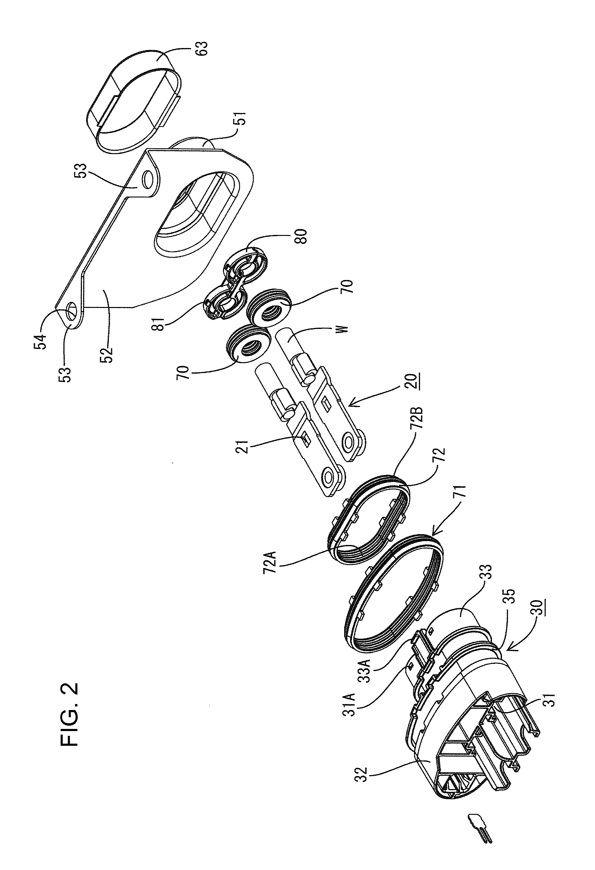
[0018]Each terminal fitting 20 is a flat plate and the wire W is connected electrically conductively to a rear part of the terminal fitting 20, as shown in FIGS. 2 and 5. Further, a locking hole 21 vertically penetrates a substantially central part of the terminal fitting 20 in forward and backward directions.

[0019]The housing 30 is a wide flat tube that is hollow in forward and backward directions, as shown in FIG. 2. The housing 30 has a large elliptical housing portion 32 at the front end and a small elliptical housing portion 33 at the rear end. The major axes of both elliptic...


PUM


Abstract

A shield connector (10) is mounted in a metal case (C) that contains a device to be mounted in a vehicle. The shield connector (10) has a housing (30) in which terminal fittings (20) connected to ends of wires (W) are accommodated and from which the wires (W) are pulled out. Rubber plugs (70) are provided for sealing between the inner peripheries of cavities (31) in the housing (30) and the outer peripheries of the wires (W). A shield shell (50) covers the housing (30) and is connected electrically to the case (C) and also to a shield conductor (60) through which the wires (W) are inserted. A second rubber ring is provided between the housing (30) and the shield shell (50).

Description

BACKGROUND OF THE INVENTION[0001]1. Field of the Invention[0002]The invention relates to a shield connector.[0003]2. Description of the Related Art[0004]U.S. Pat. No. 7,934,950 discloses a shield connector to be connected to a device mounted in a vehicle. The device is in a metal case and the shield connector is mounted to the metal case. The shield connector includes a housing for holding terminal fittings connected to wires. The wires are pulled out from the housing and a rubber seal provides sealing between the outer peripheries of the wires and the inner periphery of the housing. A tubular shield shell is mounted on the housing to cover the outer surface of the housing.[0005]The shield shell is connected electrically to the case and a shield conductor, such as a braided wire, covers the wires pulled out from the housing to provide shielding from the case to the shield conductor.[0006]A shield connector used outside a vehicle may be weathered and water may penetrate into the insi...

Claims


Application Information

Patent Timeline
Patent Type & Authority Patents(United States)
IPC IPC(8): H01R9/03
CPCH01R9/032H01R13/5202H01R13/5205H01R13/748H01R13/65912
Inventor KAWAMURA, MASAYUKI
Owner SUMITOMO WIRING SYST LTD
Why Eureka
Try Eureka