Belt tensioner with wear compensation

a belt tensioner and wear compensation technology, applied in the field of belt tensioners, can solve the problems of flexible drive being damaged, slipping off the tensioner pulley altogether, and increasing wear and tear

Active Publication Date: 2013-10-22
LITENS AUTOMOTIVE INC
View PDF66 Cites 5 Cited by
  • Summary
  • Abstract
  • Description
  • Claims
  • Application Information

AI Technical Summary

Benefits of technology

[0007]According to a first aspect of the present invention, there is provided a tensioner to tension a flexible drive, comprising: a spindle having a base and a shaft extending perpendicular thereto; a bushing having an outer frustoconical surface and an inner surface complementary to the shape of the spindle shaft, the bushing receiving the shaft in its inner surface; a tensioner arm having a pivot surface complementary to and engaging the outer frustoconical surface of the bushing to allowing the tensioner arm to pivot about a central axis of the spindle shaft, the tensioner arm further having an attachment point for a rotatable member to engage a flexible drive, the attachment point being spaced from the pivot surface; a spring acting between the spindle and the tensioner arm to bias the tensioner arm to a first pivotal position about the spindle; and a wear take up mechanism to bias the bushing towards the pivot surface to compensate for wear of the bushing and / or pivot surface.
[0008]The present invention provides a novel tensioner for use with flexible drives, such as serpentine accessory belts on automobiles or the like. The tensioner includes a tensioner arm to spindle pivot design which employs a frustoconical bushing between an inner pivot surface of the tensioner arm and a spindle shaft. The frustoconical design of the bushing resists off axis movement of the tensioner arm and a wear take up mechanism biases the bushing into contact with the inner pivot surface to compensate for normal wear of the bushing and / or pivot surface. A thrust plate is mounted to the end of the spindle shaft and rides in a thrust washer, the thrust plate and thrust washer being held captive in the tensioner arm such that the tensioner arm can pivot about the bushing and the spindle and the thrust plate and thrust washer assist in inhibiting off-axis movement of the tensioner arm.

Problems solved by technology

While such prior art tensioners are widely employed, they do suffer from some disadvantages.
In particular, due to the relatively large forces which must be carried by the tensioner arm, wear at the pivot attaching the arm to the tensioner housing is common and such wear can result in the pulley moving to an off-axis position wherein the surface of the pulley is not substantially perpendicular to the engagement surface of the flexible drive.
Such off-axis positioning of the pulley results in increased amounts of wear at the pivot and eventually will result in the flexible drive being damaged and / or slipping off the tensioner pulley altogether.

Method used


Image

  • Belt tensioner with wear compensation
  • Belt tensioner with wear compensation
  • Belt tensioner with wear compensation

Examples


Embodiment Construction

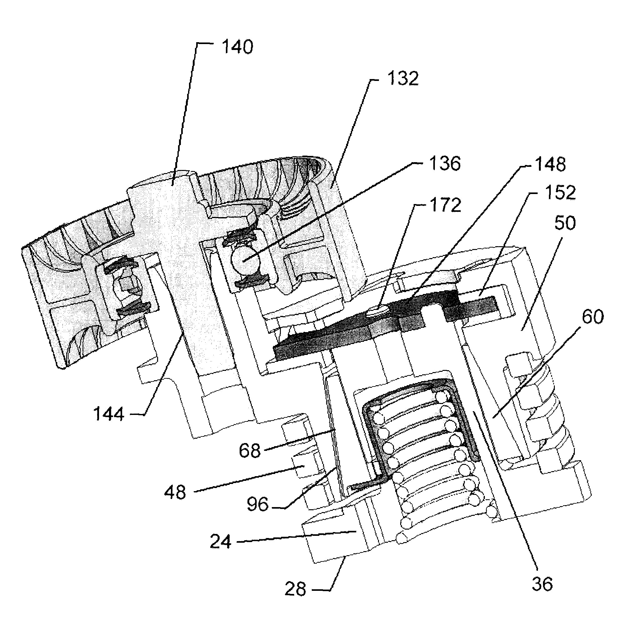
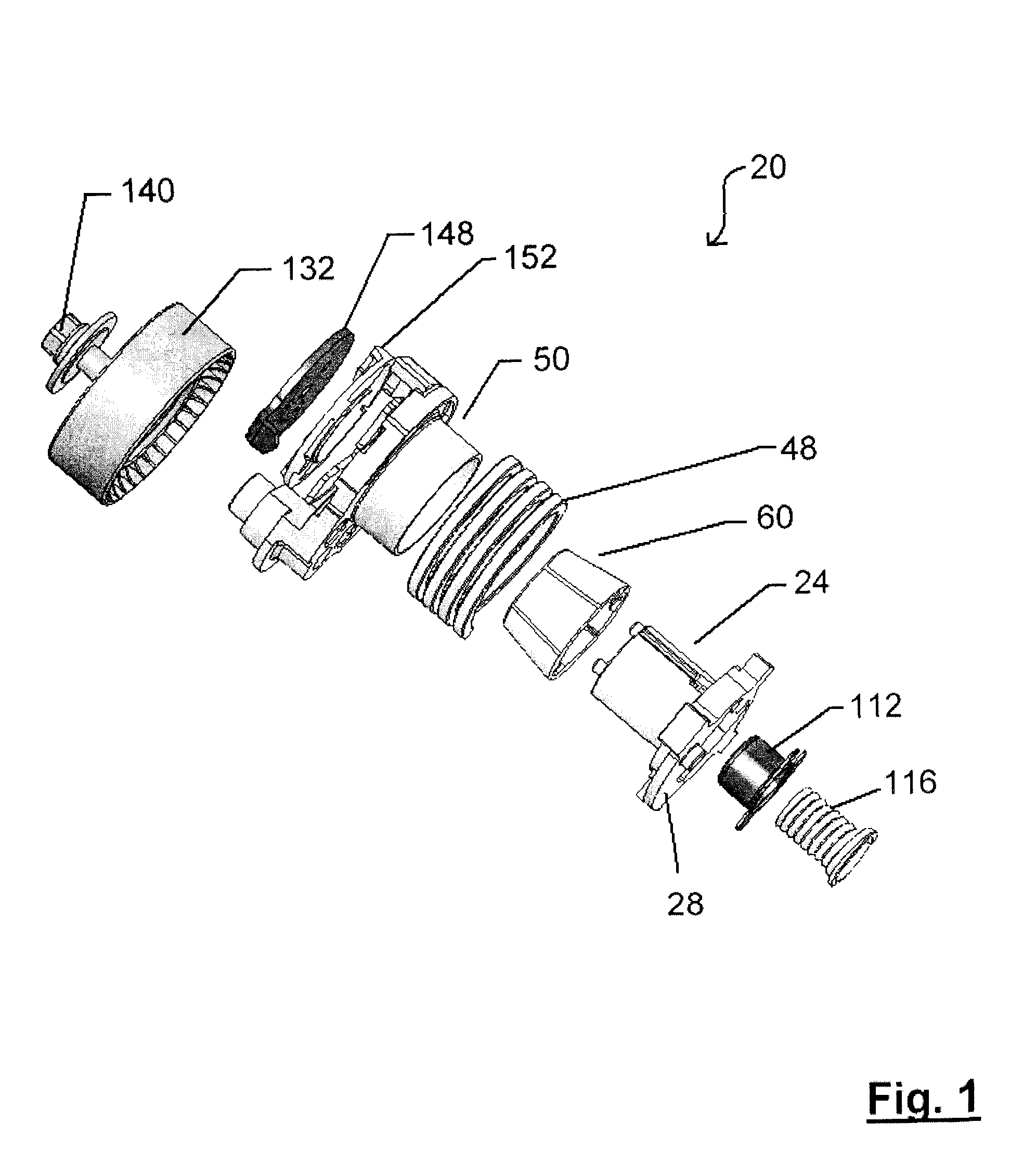
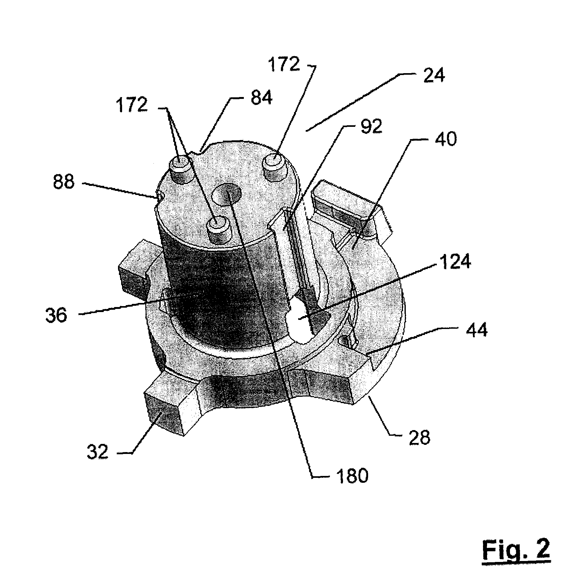
[0020]A tensioner in accordance with the present invention is indicated generally at 20 in FIG. 1. Tensioner 20 comprises a spindle 24, best seen in FIG. 2, which includes a base 28 to abut an engine (not shown) when tensioner 20 is installed. Base 28 can include one or more index features, such as tab 32, which can engage complementary features on an engine to ensure that tensioner 20 is installed in, and remains in, a desired rotational orientation on the engine. Spindle 20 further includes a cylindrical shaft 36, which extends from base 28, and a spring raceway 40 with an endstop 44.

[0021]A helical spring 48 acts between spindle 24 and a tensioner arm 50, best seen in FIGS. 3a and 3b. In the illustrated embodiment, spring 48 is expanded as tensioner arm 50 is moved from its at rest position. In this configuration, spring 48 includes a first end which abuts endstop 44 when helical spring 48 is received in raceway 40 in spindle 24 and the opposite end of helical spring 48 abuts an ...


PUM


Abstract

A novel tensioner for use with flexible drives, such as serpentine accessory belts on automobiles includes a tensioner arm to spindle pivot design which employs a frustoconical bushing between an inner pivot surface of the tensioner arm and a spindle shaft. The frustoconical design of the bushing resists off axis movement of the tensioner arm and a wear take up mechanism biases the bushing into contact with the inner pivot surface to compensate for normal wear of the bushing and / or pivot surface. A thrust plate is mounted to the end of the spindle shaft and rides in a thrust washer, the thrust plate and thrust washer being held captive in the tensioner arm such that the tensioner arm can pivot about the bushing and the spindle and the thrust plate and thrust washer assist in inhibiting off-axis movement of the tensioner arm. In one embodiment, the biasing force which biases the bushing against the inner pivot surface of the tensioner arm can be varied to change the amount of dampening of the tensioner.

Description

CROSS-REFERENCE TO RELATED APPLICATIONS[0001]This application is a 371 of PCT / CA2006 / 000422 filed Mar. 20, 2006, which claims the benefit of U.S. Provisional No. 60 / 663,853 filed Mar. 21, 2005.FIELD OF THE INVENTION[0002]The present invention relates to a tensioner which operates to maintain a substantially constant tension in a flexible drive, such as a belt or chain. More specifically, the present invention relates to a tensioner which includes means to compensate for the wear of components of the tensioner which occurs during use.BACKGROUND OF THE INVENTION[0003]Tensioners for flexible drives, such as accessory serpentine belts on automotive engines are well known. Such tensioners typically include a pulley, roller or other member, which is biased against the flexible drive by a spring or other biasing means. The pulley is mounted, via a bearing, to an arm which pivots with respect to the tensioner housing. The housing contains the spring or other biasing means which biases the a...

Claims


Application Information

Patent Timeline
Patent Type & Authority Patents(United States)
IPC IPC(8): F16H7/10F16H7/12
CPCF16H7/1218F16H7/1281F16H2007/081F16H7/12
Inventor MEVISSEN, HUBERTUS G.DELL, JAMES W.
Owner LITENS AUTOMOTIVE INC
Why Eureka
Try Eureka